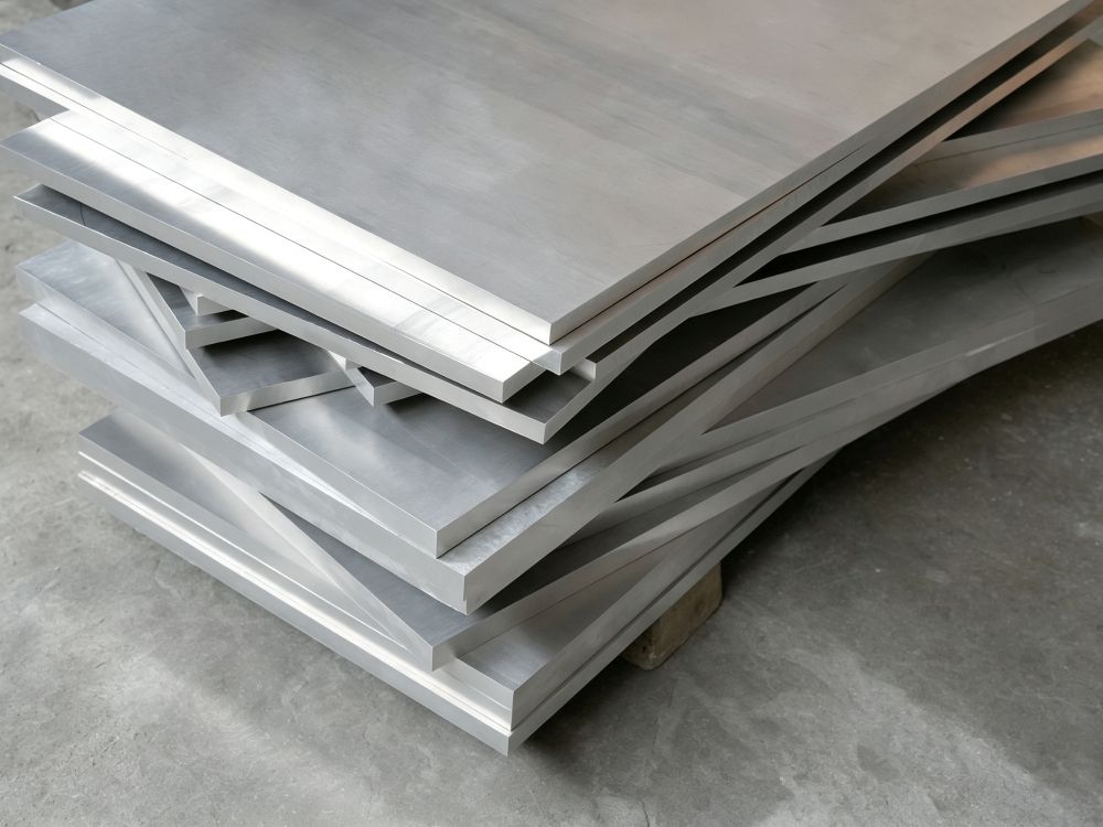
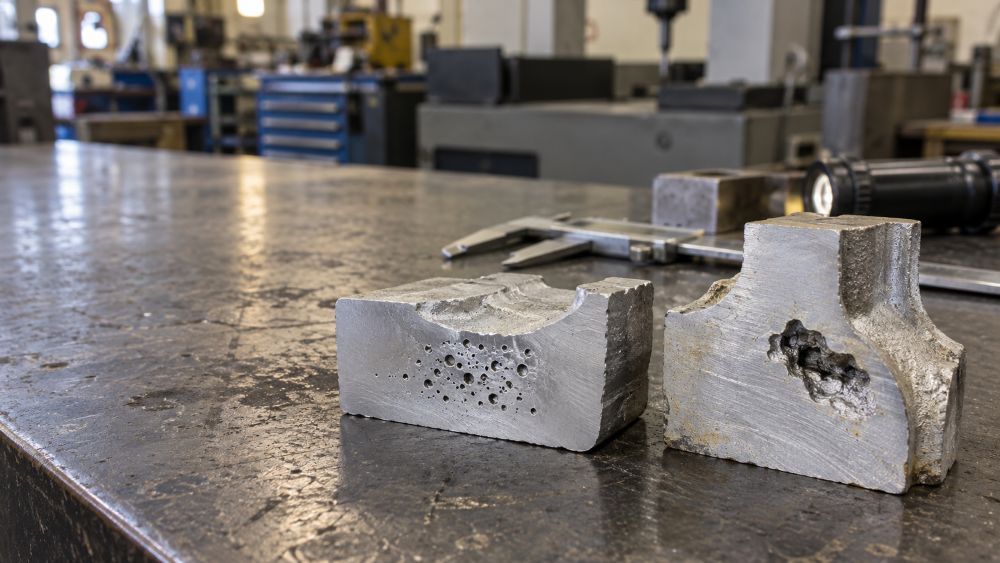
The right CNC machining tolerance is not the smallest number a supplier can write on a quote. It is the amount of variation a feature can safely accept and still do its job. Get that right and you avoid needless cost, late redesigns, and parts that look correct but do not assemble.
This guide gives practical starting points for drawings, explains where tolerance risk comes from, and shows what to discuss before production. The numbers below are planning references, not a blanket production promise. Material, geometry, datum scheme, quantity, and inspection method always need a project review.
What Are CNC Machining Tolerances?
A tolerance is the permitted variation from a nominal size. A 20.00 mm feature called out as 20.00 ±0.05 mm is acceptable from 19.95 mm to 20.05 mm. The nominal size tells the shop what you want. The tolerance tells the shop how much variation the part can live with.
Most CNC drawings use one of three styles:
| Tolerance style | Example | Best use |
|---|---|---|
| Bilateral | 20.00 ±0.05 mm | A feature can vary equally high or low |
| Unilateral | 20.00 +0.00 / −0.05 mm | One direction matters, such as a shaft or sealing land |
| Limit dimensions | 19.95–20.00 mm | Inspection needs a direct upper and lower limit |
Use a general tolerance for ordinary, noncritical dimensions. Put a specific tolerance only where fit, sealing, motion, alignment, or safety requires it. This is the simplest way to keep a drawing useful to both engineering and purchasing.
CNC Machining Tolerance Chart
The chart below is a practical quote-stage reference for common metal parts. It is not a substitute for a controlled process study. A long, thin aluminum rail and a compact steel bushing may need very different approaches even when the print shows the same number.
| Process or feature | Common planning range | Tight-tolerance planning range | What usually drives the decision |
|---|---|---|---|
| CNC milling, general profiles | ±0.10 mm | ±0.025–0.05 mm | Part size, fixture support, tool reach |
| CNC turning, turned diameters | ±0.05–0.10 mm | ±0.01–0.025 mm | Concentricity, rigidity, measurement method |
| Reamed or finish-bored holes | Project specific | ±0.01–0.025 mm | Pin, bearing, or dowel fit |
| Ground functional surfaces | Project specific | ±0.005–0.020 mm | Flatness, surface finish, mating condition |
| Threaded features | Standard callout | Class and gauge defined | Thread standard, coating, engagement |
Treat the tight-range column as a discussion starter. It may be practical, but it is not free. Ask the supplier to confirm capability on your actual feature, material, and quantity before the PO is released.
Standard vs. Precision CNC Machining Tolerances
Standard CNC machining is the right choice for most brackets, covers, housings, and non-locating features. Precision CNC machining is for the features that control how a product works: bearing seats, dowel holes, sealing faces, slide fits, and critical datum relationships.
The mistake is applying precision to every dimension. A part with twenty tight callouts can cost much more than a part with three well-chosen ones. It also takes longer to inspect. Start with function, then decide which surfaces locate, move, seal, or carry load.
For a broader process view, see our CNC precision machining process. It explains the production controls that sit behind a precision callout.
CNC Milling Tolerances: What Changes the Result?
Milling tolerances depend heavily on how the part is held. A stiff block with short tool reach is usually straightforward. A thin wall, open pocket, long rail, or part clamped only at its ends is not.
- Tool deflection: Long, small cutters can push away from a wall.
- Fixture distortion: Tight clamps can bend a thin part before machining even starts.
- Heat: Warm parts measure differently from stable, room-temperature parts.
- Datum loss: Re-clamping without a repeatable locating plan can move the relationship between features.
When a feature is critical, call out the datum faces clearly. Do not rely on a chain of ordinary dimensions. For parts that mix prismatic milling and round features, the right combination of CNC milling and turning can reduce setups and control risk.
CNC Turning Tolerances: Diameter Is Only Part of the Story
Turning is often a strong choice for diameters, bores, faces, and concentric features. But a tight diameter alone does not guarantee a good part. A shaft can be the right size and still fail if runout, shoulder squareness, surface finish, or thread position is wrong.
For a rotating component, identify the functional datum axis. Then specify only the related controls that matter. A bearing seat may need a close diameter tolerance and a surface-finish requirement. A spacer shoulder may need a controlled face relationship. An unimportant outside diameter may only need the general tolerance.
This approach makes inspection faster and gives the shop a clear target.
How Material Affects CNC Tolerance
Material changes the machining plan. Soft aluminum can move under clamping. Stainless steel can build heat and work-harden. Magnesium cuts easily, but its low stiffness and thermal response deserve careful workholding and temperature control.
The supplied magnesium-alloy reference reports a coefficient of thermal expansion of roughly 26.6–27.4 μm/(m·°C) from 20–200°C. That is a useful reminder: temperature is not a shop-floor detail when a thin or long magnesium part has a close tolerance.
| Material behavior | Tolerance risk | Practical response |
|---|---|---|
| Aluminum or magnesium, thin wall | Clamp marks and elastic spring-back | Use broad support, light clamping, and finish after stress is released |
| Stainless steel | Heat, tool wear, work hardening | Keep the tool sharp and manage heat at the cut |
| Carbon/alloy steel | Cutting load and burrs | Use rigid workholding and realistic edge requirements |
| Plastic | Temperature and moisture movement | Confirm the measurement condition and functional environment |
For magnesium projects, our magnesium CNC machining guide covers material-specific production concerns. The short version is simple: do not copy settings from aluminum and assume the result will be the same.
Magnesium end-milling data from the supplied reference
The historical textbook pages supplied for this article list the following end-milling guidance for magnesium alloys. These are reference data from the source, not Miji production parameters or a process guarantee. Tool geometry, alloy, machine condition, coolant, chip control, and part safety must be reviewed before use.
| Operation | Tool material | Cutting speed | Feed per tooth |
|---|---|---|---|
| Rough end milling | HSS | 245 m/min | 0.10–0.28 mm/tooth, by cutter diameter |
| Finish end milling | HSS | 305 m/min | 0.08–0.20 mm/tooth, by cutter diameter |
| Rough end milling | Carbide | Source lists “maximum” | 0.10–0.30 mm/tooth, by cutter diameter |
| Finish end milling | Carbide | Source lists “maximum” | 0.08–0.23 mm/tooth, by cutter diameter |
What Causes CNC Tolerance Variation?
Tolerance variation usually comes from a system, not one bad number. Machine positioning, fixture repeatability, tool wear, programming, part temperature, cutting load, and measurement all interact.
The most useful question is not “Can you hold ±0.02 mm?” Ask instead: “Which feature needs it, how will it be held, and how will it be measured?” That conversation reveals risk early.
Temperature is a frequent blind spot. A part may come off the machine warm, pass a quick check, and shift after it cools. Read more about how temperature affects CNC accuracy, especially for long parts and close fits.
How Tighter Tolerances Affect CNC Machining Cost
Tight tolerances increase cost because they require more control. The shop may need slower finishing cuts, a dedicated fixture, extra probing, tool changes, in-process checks, a controlled measurement room, or grinding after machining.
That does not mean you should avoid tight tolerances. It means each one should earn its place. A bearing bore is worth controlling. A cosmetic outer edge usually is not. If only one area of a housing locates another part, hold that area tightly and relax the rest.
The best savings often happen before machining starts. A focused drawing can eliminate extra setups and inspection without compromising function.
How to Specify Tolerances and Inspect Them
Start every drawing with a clear unit system, revision, material, finish, and general tolerance block. Then add specific dimensions and geometric controls only where the assembly needs them.
- Identify the functional datums.
- Mark features that locate, seal, rotate, or mate with another part.
- Use bilateral, unilateral, or limit tolerances deliberately.
- State the thread standard, fit class, and coating condition where needed.
- Avoid demanding a number that your assembly does not need.
- Define the inspection method for the few features that truly matter.
A caliper is fine for a basic external check. A micrometer, bore gauge, pin gauge, height gauge, optical system, or CMM may be needed for a critical feature. The right method depends on the tolerance, geometry, datum, and volume.
It also helps to separate three terms that are often mixed up: accuracy, precision and repeatability. A machine can repeat a motion well and still make an inaccurate part if the setup or compensation is wrong.
A Practical Quoting Example
Consider a magnesium electronics housing with a 20.00 mm locating bore, a flat sealing face, and several cosmetic outer walls. The bore may need a specific fit range. The sealing face may need flatness and finish control. The outside walls may only need a general tolerance.
Putting ±0.02 mm on every wall would add cost without improving the product. A better print controls the bore from a stable datum, defines the sealing surface, and lets the shop use normal capability on the rest. That is the kind of drawing that receives a quicker, clearer quote.
This is an engineering example, not a published customer result. Final tolerances should be reviewed against the mating parts, assembly method, and production quantity.
Frequently Asked Questions
What is a standard CNC machining tolerance?
For many general metal features, ±0.10 mm is a common starting point. The correct value depends on the size, material, process, and function of the feature.
What is a tight CNC machining tolerance?
It is a tolerance that needs more control than routine machining. In many projects, ±0.025 mm or tighter deserves a process and inspection discussion before production.
Can every CNC feature hold ±0.01 mm?
No. Some features can, but geometry, tool access, material, part stability, and inspection must support it. A close number on paper is not enough.
Do milling and turning use the same tolerance?
Not always. Turning is naturally suited to many round, concentric features. Milling is often better for planes, pockets, and profiles. The functional feature should choose the process.
Does ISO 2768 replace specific tolerances?
No. ISO 2768 can support general tolerances for unspecified dimensions. Critical fits, datums, hole positions, flatness, and surface requirements still need clear individual callouts.
Why do close tolerances cost more?
They can add setups, slower cuts, special tooling, inspection, and scrap risk. The cost is usually worth it only when the function requires it.
How should I request a CNC machining quote?
Send a 3D model, a dimensioned drawing, material and finish requirements, quantity, and the features that are truly critical. You can request a machining review when you want help separating essential tolerances from unnecessary ones.
Final Takeaway
Good CNC machining tolerances are functional, measurable, and realistic. Tighten the dimensions that make the assembly work. Relax the ones that do not. That balance is what gives you reliable parts without paying for control you never use.