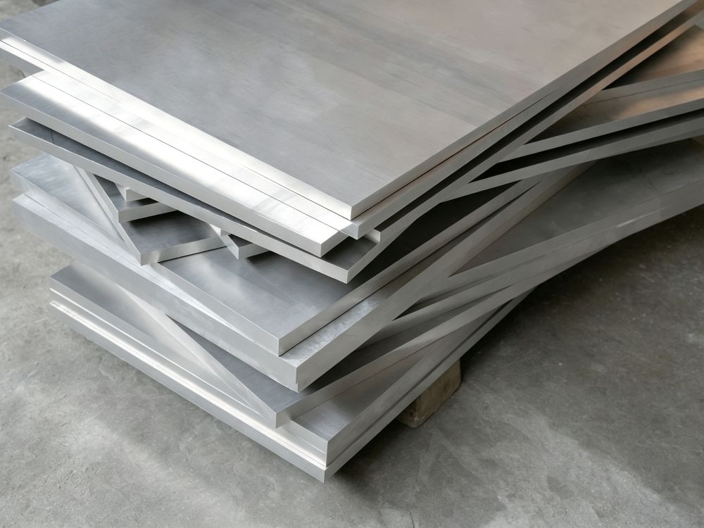
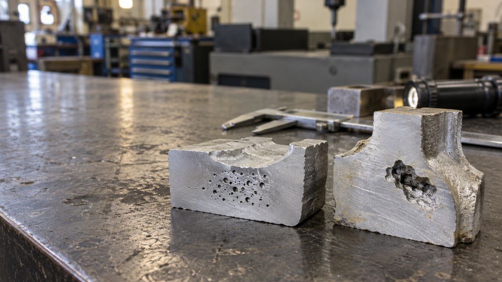
Temperature affects CNC accuracy because metal expands when it gets warmer and contracts when it cools. Heat can come from cutting, the spindle, the fixture, coolant, a warm measuring area, or simply a part sitting near a machine. On ordinary parts, the change may not matter. On tight bores, sealing faces, long parts, thin walls, or matched assemblies, it can move a feature enough to create inspection failures or poor fit. The answer is not always climate control. It is matching temperature control and measurement practice to the real risk of the part.
Why a Stable Machine Can Still Produce a Size Shift
A machine can be calibrated and still produce a part that changes size after machining. The machine may be correct, but the part is warmer than the drawing’s reference condition.
This happens most often when a feature is finished immediately after heavy roughing. The part has absorbed heat. A bore measured while warm may appear correct, then become smaller when it returns to room temperature. The opposite can happen if a cold part is measured in a warmer area.
The fixture can create a second problem. A hot fixture can expand or hold the part differently. When the clamps are released, a thin component may relax and show a different flatness or position result.
For the full control system around tolerances, inspection, setup, and process planning, see Precision CNC Machining.
Where Heat Enters the CNC Process
Heat rarely comes from one source. It normally builds from several small sources at once.
Cutting creates heat at the tool edge and in the workpiece. High material removal rates, dull tools, poor chip evacuation, and long tool engagement raise that heat quickly. Coolant helps, but it cannot always keep a thin or delicate feature at a uniform temperature.
The spindle warms during a long production run. So do ball screws, drives, fixtures, and nearby equipment. A machine that has just started its shift can behave differently from the same machine after several hours of use.
Measuring is also part of the process. A part brought from a warm machine directly to a cool inspection room may not be at a stable temperature. The measuring tool, gauge block, and part must be considered together on critical work.
| Heat source | What may move | Simple control method |
|---|---|---|
| Heavy roughing | Bore size, wall thickness, flatness | Leave stock, let the part stabilize, then finish |
| Spindle warm-up | Tool position and length compensation | Warm up before critical production work |
| Clamp pressure and hot fixtures | Flatness, parallelism, feature position | Use stable locating points and controlled clamping |
| Hot or cold inspection area | Measured size | Allow critical parts to stabilize before final measurement |
| Tool wear and rubbing | Local heat, finish, hole size | Monitor tools and avoid excessive dwell or rubbing |
This is why a practical precision plan considers the full route from first setup to final inspection, not just the cutting cycle.
Useful Thermal Expansion Numbers for Planning
The numbers below are approximate room-temperature linear expansion values. They are real engineering planning data, but each alloy grade, heat treatment, temperature range, and part geometry must be confirmed for the actual order.
| Material | Approx. linear expansion coefficient (µm/m/°C) | Size change across 100 mm for a 10°C change |
|---|---|---|
| Carbon steel | 11.7 | 0.012 mm |
| Aluminum alloy | 23.6 | 0.024 mm |
| AZ31 magnesium alloy | about 26 | about 0.026 mm |
| Titanium alloy | 8.6 | 0.009 mm |
The calculation is simple: length × expansion coefficient × temperature change. For example, a 100 mm magnesium feature can change by roughly 0.026 mm across a 10°C difference. That may be irrelevant for a loose cover plate. It is not irrelevant for a tight location feature or a tolerance band close to that value.
Longer parts increase the effect. A 500 mm aluminum rail exposed to the same 10°C difference can shift by about 0.118 mm. This is why long profiles, frames, optical mounts, and multi-hole patterns need a clear datum and measurement plan.
For more on how stable results differ from a one-off passing measurement, read CNC Accuracy vs Precision vs Repeatability.
Parts That Need Extra Thermal Attention
Not every part needs special temperature control. The key question is whether a small size change affects function.
Give extra attention to bearing bores, locating pins, matched hole patterns, sealing faces, long precision rails, thin-wall housings, and parts assembled with components made elsewhere. These features can fail even when every individual dimension looks close to nominal.
Magnesium and aluminum parts deserve a closer look because they expand more than steel. They are also often designed with thin walls to reduce weight. That combination makes fixturing, machining sequence, and release from the fixture important.
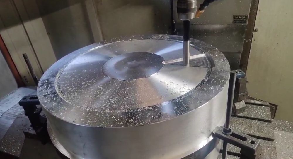
When wall thickness is low, the order of operations matters. Roughing one side, flipping immediately, and finishing the other side can lock in distortion. CNC Machining Thin Wall Deflection covers practical steps that reduce this risk.
What Buyers Should Put on the Drawing or RFQ
You do not need to write “temperature controlled” on every drawing. Start with the critical features and the function they control.
State the tolerance, datum reference, required surface finish, and inspection requirement. If a feature is temperature sensitive because of length, material, or fit, note the operating or inspection condition. This helps the supplier choose the right fixture, machining sequence, finishing allowance, and measurement approach.
Use this short checklist when requesting a quote:
- Mark the features that control fit, sealing, alignment, or movement.
- Provide a STEP/STP model and a PDF drawing with datums and GD&T where needed.
- Identify material grade, including whether a specific magnesium or aluminum alloy is required.
- State the inspection documents needed: first article, CMM report, material certificate, or batch record.
- Tell the supplier whether parts must interchange across batches or with another supplier’s components.
- Include quantity, target date, and delivery country.
This level of information gives a shop a chance to prevent thermal drift before cutting starts. For a tolerance review or documented production quotation, request an instant quote.
Material Certificates Support Traceability, Not Dimensional Proof
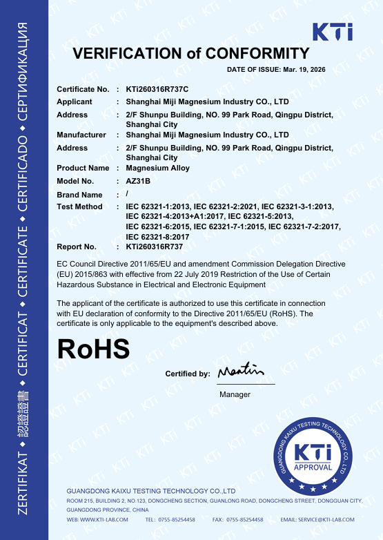
Material records are useful when they are tied to the purchased alloy. The supplied AZ31B RoHS certificate is shown below as a real example of material-compliance documentation.
It identifies AZ31B magnesium alloy, certificate No. KTi260316R737C, and an issue date of March 19, 2026. This supports material and RoHS compliance review. It does not prove that a warmed part was measured at a stable temperature or that a machined bore meets the drawing.
For that, buyers should request the right dimensional evidence: a first-article report for the initial part, a CMM report for defined critical features, and in-process or batch checks where repeatability matters. The right documents depend on the part’s risk, not on a standard list copied to every purchase order.
A Straightforward Rule for Cost and Risk
The goal is not to control every degree of temperature on every job. The goal is to control the temperatures that could move a critical feature outside its useful range.
For normal brackets, covers, and clearance features, general machining practice is usually enough. For long, thin, tight-fitting, sealing, or safety-related parts, a little extra planning can prevent expensive sorting, rework, or field failures.
Ask your supplier one simple question: “Which dimensions are most likely to move as this part warms and cools, and how will you inspect them?” A capable supplier should answer clearly before production begins.
Capability note: Thermal expansion values in this guide are for planning. Confirm the applicable material data, drawing tolerance, inspection condition, and stable factory capability before releasing production.