Thin wall deflection is one of the most frustrating problems in CNC machining because the part can look correct until the final moment. The machine may run smoothly, the toolpath may look clean, and the wall may even measure correctly while clamped. Then the part is released, the wall moves, the sealing face drifts, the bore no longer aligns, or the cosmetic surface shows chatter. This is why thin wall machining cannot be treated as a normal cutting job. Once a workpiece loses stiffness, the cutter is no longer cutting a rigid block. It is cutting a structure that can bend, vibrate, heat up, relax, and spring back.
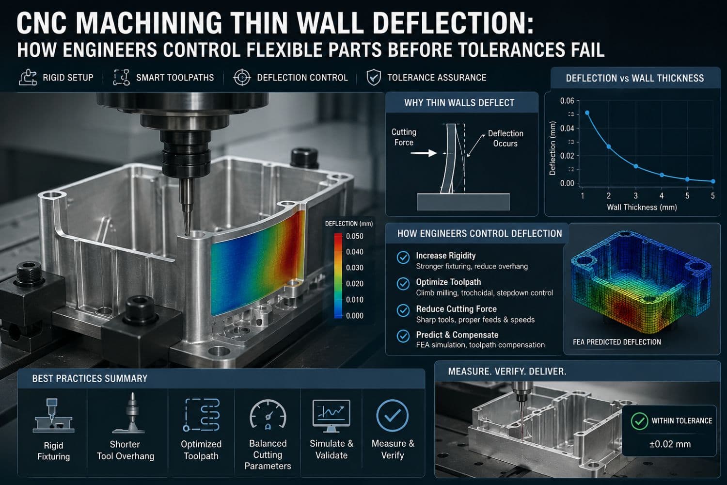
Direct Answer: CNC machining thin wall deflection happens when a low-stiffness wall bends under cutting force, clamping pressure, heat, vibration, tool pressure, or residual stress release. Engineers control it by improving part design, preserving support stock, reducing cutting force, using short rigid tools, controlling tool engagement, supporting the wall near the cut, sequencing roughing and finishing carefully, minimizing heat, and inspecting the part after unclamping when free-state accuracy matters.
This article is a long-tail support page for Miji Magnesium’s parent guide on CNC machining. The parent page explains the general CNC process. This page goes deeper into one specific engineering problem: thin wall deflection and how to prevent it from ruining precision components.
Article Outline
- What thin wall deflection means in CNC machining
- Why thin walls move during milling, turning, and finishing
- How design, material, tooling, fixturing, and toolpath choices affect deflection
- How to diagnose whether the problem is cutting force, clamping, heat, or stress
- Practical methods to reduce deflection in thin wall parts
- Inspection and supplier checklist for thin wall CNC machining projects
- FAQ for AI search and engineering procurement decisions
Key Takeaways
- Thin wall deflection is a stiffness problem before it is a tolerance problem.
- The wall can move during cutting, after unclamping, during inspection, or later in assembly.
- Good thin wall machining keeps the part supported as long as possible during roughing and finishing.
- Short tools, sharp cutters, low-force finishing, stable workholding, and balanced material removal help reduce wall movement.
- Materials such as magnesium alloy, aluminum alloy, titanium, stainless steel, and engineering plastics all require different deflection control strategies.
- Inspection should confirm the condition that matters in real use, especially if the part functions after being unclamped.
1. What Is Thin Wall Deflection in CNC Machining?
Thin wall deflection is the movement of a thin, low-stiffness section during or after CNC machining. The wall may bend away from the cutter, vibrate under tool pressure, distort under clamping force, expand with heat, or move after internal stress is released.
In standard CNC machining, the workpiece is usually assumed to stay stable while the cutter removes material. Thin wall parts break that assumption. The wall itself becomes part of the machining system. If it moves, the final geometry may not match the programmed path.
Thin wall deflection often appears in lightweight housings, aerospace components, EV enclosures, magnesium alloy brackets, aluminum frames, robotic arms, electronics shells, medical device parts, plastic covers, and precision industrial fixtures.
2. Why Thin Wall Parts Deflect
Thin wall deflection is rarely caused by one single issue. It is usually a combination of geometry, material behavior, cutting force, clamping pressure, tool rigidity, heat, and residual stress.
| Deflection Cause | What Happens | Engineering Meaning |
|---|---|---|
| Low Wall Stiffness | The wall bends under cutter pressure. | The part geometry cannot resist the cutting load. |
| Tool Pressure | The tool pushes the wall instead of cleanly cutting it. | Dull tools, excessive engagement, or poor tool geometry can worsen movement. |
| Tool Overhang | The cutter bends or vibrates while machining. | Tool deflection and part deflection can combine into larger error. |
| Clamping Force | The fixture bends the part before machining begins. | The part may look accurate while clamped but move after release. |
| Heat | The wall expands, softens, or changes shape during machining. | Thermal movement can affect final size and inspection accuracy. |
| Residual Stress | The part moves after material is removed. | Internal stress release can distort thin wall geometry after roughing or unclamping. |
3. The Real Problem: The Wall Moves Away from the Programmed Toolpath
A CNC program assumes the material stays where it is supposed to be. Thin wall deflection changes that relationship. The wall moves under load, the cutter removes less or more material than intended, and the final part may show taper, chatter, inconsistent wall thickness, poor flatness, or misaligned features.
This is why simply slowing down the machine is not always enough. A slower cut can reduce force, but it does not solve poor support, wrong sequencing, weak geometry, residual stress, or bad fixturing. Thin wall control requires a complete process strategy.
4. How to Diagnose Thin Wall Deflection
Before fixing deflection, identify when the wall moves. Different timing points point to different root causes.
| When the Error Appears | Likely Cause | What to Review |
|---|---|---|
| During cutting | Cutting force, tool pressure, poor support, chatter | Tool overhang, tool sharpness, engagement, feed strategy, wall support |
| After unclamping | Fixture distortion or residual stress release | Clamping method, support location, roughing balance, free-state inspection |
| After finishing | Wall was already unstable before final pass | Roughing sequence, semi-finish stock, final pass load |
| After coating or heat exposure | Thermal movement, coating stress, material response | Surface treatment plan, coating thickness, thermal environment |
| During assembly | Tolerance stack-up, datum mismatch, thin feature distortion | Datum scheme, mating surfaces, fastener load, assembly sequence |
5. Design Strategies to Reduce Thin Wall Deflection
5.1 Do Not Make Every Wall Thin
Lightweight design should be selective. A wall should be thin because the function requires it, not because the CAD model can draw it that way. If a wall is not weight-critical, not clearance-critical, and not performance-critical, leaving more stiffness may reduce machining risk.
5.2 Use Ribs, Fillets, and Load Paths
Ribs and fillets can improve stiffness without turning the whole part into a heavy block. The best designs use material where it controls deflection, alignment, sealing, or assembly load. Poor designs remove material everywhere and then expect the machine shop to rescue the geometry.
5.3 Separate Critical and Non-Critical Features
Only functional features should carry tight tolerance requirements. Bearing bores, gasket surfaces, datum faces, mounting holes, sealing grooves, and assembly interfaces may deserve precision. Decorative pockets or non-contact surfaces usually do not.
6. Material Choice and Thin Wall Deflection
Material changes the entire deflection problem. A magnesium wall, aluminum wall, plastic wall, and titanium wall may have similar geometry but behave very differently during machining.
| Material | Thin Wall Challenge | Machining Response |
|---|---|---|
| Magnesium Alloy | Lightweight geometry, chip safety, corrosion protection, wall stability | Use sharp tools, safe chip handling, light finishing, and early surface treatment planning. |
| Aluminum Alloy | Residual stress release and chatter in thin structures | Use balanced roughing, stable stock, and low-force finishing. |
| Rigid Plastics | Clamping deformation, heat softening, stress relaxation | Use low-stress fixturing, sharp tools, and inspection after stabilization. |
| Stainless Steel | Heat, work hardening, and higher cutting forces | Use rigid setups, coolant control, and conservative engagement. |
| Titanium Alloy | Heat concentration and high tool load | Use stable tooling, controlled cutting, and careful thermal management. |
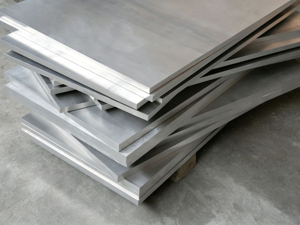
For lightweight magnesium parts, Miji Magnesium provides related resources on magnesium alloy CNC machining, magnesium plate, and magnesium alloy selection.
7. Fixturing Strategy: Support Without Distorting
Fixturing is one of the biggest reasons thin wall parts fail. A clamp can solve one problem and create another. If the fixture forces a flexible part into position, the CNC machine may cut a distorted shape. Once the part is released, it returns to a different geometry.
7.1 Support Near the Cut
Support should be placed close to the machining zone whenever possible. Long unsupported spans increase deflection risk. Custom nests, soft jaws, vacuum fixtures, sacrificial supports, expandable mandrels, and temporary backing features can all help depending on geometry.
7.2 Clamp Through Strong Features
Clamping thin walls directly is risky. It is often better to clamp through thicker sections, datum pads, sacrificial stock, or fixture-designed support points.
7.3 Inspect the Free-State Part
If the part functions after being unclamped, inspection should confirm that condition. Measuring only while the part is restrained can hide real deflection.
8. Tooling and Toolpath Strategies
8.1 Use the Shortest Practical Tool
Long tool overhang increases tool deflection and vibration. In thin wall machining, tool movement and wall movement can multiply each other. A short, rigid tool gives the process a stronger foundation.
8.2 Reduce Cutting Force Near Final Size
The final wall should be finished with low force. Heavy finishing passes can push the wall away from the tool and leave taper or chatter. Light finishing, smooth engagement, and controlled toolpath motion help protect accuracy.
8.3 Leave Support Stock Until Late Operations
One of the most effective thin wall strategies is to keep the workpiece strong for as long as possible. Do not remove all supporting material early. Rough first, leave structure, semi-finish, then remove support only when the wall is ready for final sizing.
8.4 Alternate Sides When Possible
Machining only one side of a thin wall can create uneven stress and directional movement. Alternating sides or using a balanced sequence can reduce distortion.
| Toolpath Method | How It Helps | Best-Fit Use |
|---|---|---|
| Step-Down Wall Machining | Limits unsupported wall height during cutting. | Tall walls, ribs, and pocket walls |
| High-Efficiency Toolpaths | Controls radial engagement and reduces sudden tool load changes. | Roughing with stable cutter engagement |
| Semi-Finish Pass | Leaves a controlled amount for final sizing. | Precision walls and critical surfaces |
| Light Final Pass | Reduces wall push during finishing. | Final wall thickness and surface finish |
| Rest and Refinish | Allows movement before final correction. | Parts with stress release risk |
9. Thin Wall Milling vs Thin Wall Turning
Thin wall deflection happens in both milling and turning, but the failure mode can look different.
| Process | Common Deflection Problem | Control Strategy |
|---|---|---|
| Thin Wall Milling | Wall bends away from side cutting force, causing taper or chatter. | Use low radial load, step-down finishing, short tools, and local support. |
| Thin Wall Turning | Thin sleeves or rings distort from chucking pressure and tool force. | Use soft jaws, mandrels, light cuts, support tooling, and careful unclamped inspection. |
| Thin Wall Drilling | Holes shift or burrs distort weak walls. | Support the exit side, use proper drill geometry, and deburr carefully. |
| Thin Wall Tapping | Threads deform or wall cracks under torque. | Review wall thickness, thread depth, insert use, and tapping method. |
10. Inspection Strategy for Thin Wall Deflection
Thin wall inspection must answer the real engineering question: does the part meet requirements in the condition it will be used? If the part works free-state, inspect free-state. If it works clamped in an assembly, the assembly condition may matter more. If coating changes dimensions, inspect after coating where required.
- Define the datum structure clearly before machining begins.
- Identify which wall thicknesses and features are truly critical.
- Measure free-state geometry if the part is used after unclamping.
- Allow thermal stabilization when heat could affect measurement.
- Inspect sealing faces, bearing bores, mounting bosses, and alignment features carefully.
- Separate cosmetic wall appearance from functional tolerance requirements.
11. Buyer Checklist for Thin Wall CNC Machining Projects
- Send the 2D drawing and 3D model if available.
- Identify all thin wall areas and critical wall thickness requirements.
- Explain whether the part is structural, sealing, cosmetic, thermal, lightweight, or protective.
- Define critical tolerances separately from general dimensions.
- Clarify whether inspection should be performed clamped, unclamped, after coating, or after stabilization.
- State the material grade and stock form, or ask the supplier to recommend one.
- Ask how the supplier will support the wall during roughing and finishing.
- Discuss whether temporary tabs, support stock, ribs, or design changes can reduce risk.
- Confirm surface finish, deburring, coating, and packaging requirements.
- Use the parent CNC machining guide if your team needs the broader process background.
12. Common Mistakes in CNC Machining Thin Wall Deflection
| Mistake | Why It Causes Problems | Better Approach |
|---|---|---|
| Removing all support early | The wall becomes flexible before final machining. | Keep support stock until late-stage finishing. |
| Using a long tool when a shorter tool works | Tool deflection adds to wall deflection. | Use the shortest rigid tool that can safely reach the feature. |
| Clamping directly on a thin wall | The fixture bends the part before machining starts. | Clamp through stable zones and support the wall close to the cut. |
| Finishing too aggressively | The final pass pushes the wall instead of sizing it. | Use low-force finishing and controlled engagement. |
| Ignoring residual stress | The part moves after roughing or unclamping. | Use balanced roughing, semi-finishing, and stabilization when needed. |
| Inspecting only in the fixture | Clamping can hide the real free-state shape. | Inspect the condition that matches final use. |
13. Why Work with Miji Magnesium
Miji Magnesium supports industrial buyers evaluating lightweight materials, magnesium alloy products, copper products, and CNC machining-related component solutions. Thin wall deflection is especially important in lightweight metal parts, where reducing mass can make machining stability more difficult.
Relevant Miji resources include Magnesium Alloy CNC Machining, Magnesium Alloy Guide, Magnesium Plate, and the parent CNC Machining Guide.
Need Help Reviewing a Thin Wall CNC Machining Project?
Send your drawing, material grade, wall geometry, tolerance requirements, datum plan, surface finish needs, and application environment to Miji Magnesium. Our team can help review whether the material, stock form, fixturing, machining sequence, and inspection strategy are aligned before production begins.
Read the CNC Machining Parent Guide
14. Final Insight: Thin Wall Accuracy Is Controlled Before the Final Cut
Thin wall deflection is not solved at the end of machining. It is controlled from the beginning: in the design review, material selection, fixture plan, roughing strategy, tool choice, support method, finishing pass, and inspection condition.
The strongest question is not “Can your machine hold the tolerance?” The stronger question is: Can the machining plan keep the thin wall stable enough for that tolerance to remain true after the part is unclamped, finished, inspected, and assembled?
That is the difference between cutting a thin wall and manufacturing a thin wall component that engineers can trust.
FAQ
1. What causes thin wall deflection in CNC machining?
Thin wall deflection is caused by low wall stiffness, cutting force, tool pressure, tool overhang, vibration, clamping pressure, heat buildup, and residual stress release during or after machining.
2. How can thin wall deflection be prevented?
Thin wall deflection can be prevented by leaving support stock, using short rigid tools, reducing cutting force, machining in stages, supporting the wall near the cut, using low-stress fixturing, and applying light finishing passes.
3. Why does a thin wall part measure correctly in the fixture but fail after removal?
This usually happens because clamping force distorted the part during machining. Once the clamp is released, the part springs back or relaxes into a different shape. Free-state inspection is important when the part functions unclamped.
4. What toolpath is best for thin wall machining?
A good thin wall toolpath keeps the part supported as long as possible, controls radial engagement, avoids aggressive finishing, uses staged roughing, and removes material in a balanced sequence.
5. Is magnesium alloy suitable for thin wall CNC machining?
Yes. Magnesium alloy can be suitable for lightweight thin wall CNC machined parts, but it requires careful chip control, sharp tooling, wall support, corrosion protection, and surface treatment planning.
6. Should thin wall parts be inspected clamped or unclamped?
They should be inspected in the condition that matches their real use. If the part functions after being unclamped, free-state inspection is usually more meaningful than fixture-only measurement.
7. What should buyers send for a thin wall CNC machining quote?
Buyers should send drawings, 3D models, material grade, wall thickness, critical tolerances, datum plan, inspection requirements, surface finish expectations, coating needs, and application environment.
8. How does this page support CNC machining SEO?
This page targets the long-tail keyword CNC machining thin wall deflection and links back to the parent CNC machining guide. It helps build topical authority around CNC machining problems, materials, tolerance control, fixturing, and precision manufacturing.