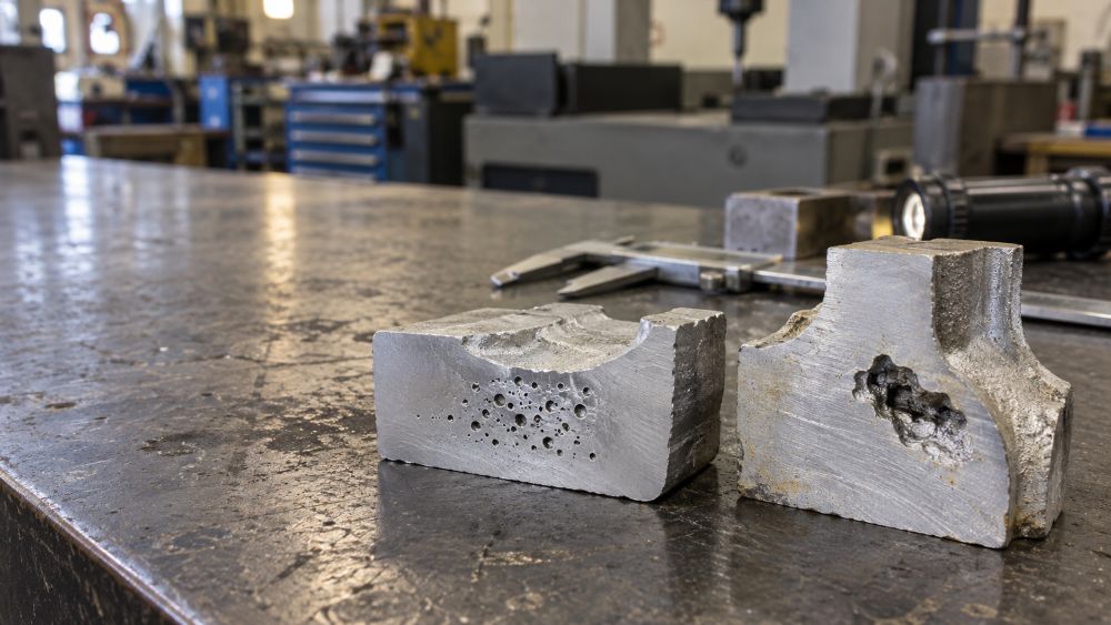
Gas porosity and shrinkage porosity can both leave voids inside a casting, yet they start from different problems. Gas-related voids are tied to gas entering, becoming trapped in, or coming out of the metal and mold system. Shrinkage porosity develops when metal contracts during freezing and a late-solidifying area cannot receive enough feed metal. A rounded pore or a rough cavity can point the investigation in a direction, but it is not a final diagnosis by itself.
The useful question is not simply, “What does this hole look like?” Start with where it sits in the part, what section froze last, how the metal entered the cavity, and what the melt, mold, core, and pour records show. That is how a defect review becomes more than a guess based on one cut surface.
Gas Porosity vs Shrinkage Porosity
Gas porosity is commonly associated with dissolved gas, air entrainment, mold or core gases, moisture, binder breakdown, poor venting, or a turbulent fill that folds air into the stream. The pores may be near the surface, around a core, near a flow meeting point, or in a high area where air had little chance to escape. The exact pattern changes with the casting and process.
Shrinkage porosity follows the solidification pattern. A heavy junction, pad, boss, or section change can remain liquid after surrounding metal has already begun to freeze. If the riser or feed path has closed off, the last liquid has nowhere to come from. The result can be a rough, irregular internal cavity or a fine cluster of shrinkage between dendrites.
| What you observe | More consistent with gas-related porosity | More consistent with shrinkage porosity | What the team should review |
|---|---|---|---|
| Cavity surface | Often rounded or smoother | Often irregular, rough, or interdendritic | A sectioned sample; shape is a clue, not proof |
| Part location | Near cores, surfaces, high points, flow joins, or poor vents | In thick sections, hot spots, and last-to-freeze regions | Mold/core layout, section map, and solidification path |
| Process trail | Melt handling, moisture, binder, venting, turbulence, or air pickup | Riser performance, feed path, local cooling, and thermal mass | Actual production records, not only the drawing |
| Best next check | Gas and mold-control review plus internal inspection | Feeding and solidification review plus internal inspection | Compare several parts from the same lot where possible |
This distinction matters because the wrong correction wastes time. More feeding metal will not stop gas from a wet core. Better venting will not feed a thick boss that has become isolated during solidification.
Where the Gas and the Metal Feeding Problem Start
For gas porosity, look upstream before blaming the mold. Was the melt held too long? Was the surface disturbed during transfer? Did treatment, skimming, or degassing follow the qualified route? Were mold and core materials at their required condition? A sand mold can look dry on the outside and still release gas where a core, binder, coating, or local moisture problem is concentrated.
Metal flow deserves the same attention. A stream that falls freely, strikes a wall hard, or splits and reunites can carry air and oxide films into the cavity. In magnesium work, melt quality and oxidation control need to be reviewed alongside filling behavior. Our guides to magnesium alloy melting defects control and magnesium melt treatment and casting defect control cover that earlier part of the route. For sand-related sources, see magnesium alloy casting sand gas porosity.
Shrinkage starts with the thermal layout of the part. The casting may have an obvious heavy area, but the difficult spot is sometimes a smaller junction where several walls meet. A riser has to remain connected to that region while it freezes. Local chills, wall transitions, riser necks, and the order in which nearby sections solidify all change the outcome.
This is why a solidification review should use the real section map, not a general rule based only on overall casting weight. Two parts with the same weight can have completely different feeding problems.
Reading the Defect Location and Process Record
When a casting leaks or an X-ray shows a void, mark the exact location on a drawing before cutting another sample. Note the distance from the gate, riser, core print, parting line, and thick-section transition. The location often gives more information than the first close-up photo of the cavity.
For example, a defect found repeatedly in the center of a heavy flange should immediately trigger a feeding review. A group of small, rounded voids close to a core surface calls for a different set of checks: core condition, venting, binder, coating, and fill behavior. Neither example is a shortcut to a final conclusion. They are practical places to begin.
The production record can separate an isolated setup problem from a repeatable process issue. Useful records include alloy and melt batch, treatment and holding time, mold/core identification, moisture or permeability tests where applicable, pouring temperature and time, and any gate, filter, riser, or chill revision. A defect review is much easier when these details were captured on the day the parts were poured.
Mixed defects are possible. A rough cavity may include oxide films. A hot area may also be where gas is trapped because the fill path and venting were poor. Treating every void as either “gas” or “shrink” from appearance alone can send the trial in the wrong direction.
Gating, Pouring, Filters, and Risers
The book cases behind this article show a familiar foundry lesson: flow control and feeding control have to work together. In frame- and housing-type castings, changing the flow route, reducing local impact, distributing entry points, and adding filtration were used to reduce oxide-inclusion problems. Those changes helped the metal enter more steadily and limited the chance of pulling surface films into the casting.
That does not turn the published gate areas or layouts into a universal recipe. The right inlet position depends on the part shape, mold orientation, alloy, section thickness, core arrangement, and feeding plan. A casting gate location and ingate placement review should be tied to the actual model. The same applies to aluminum and magnesium gating ratio; a ratio is a starting design relationship, not a replacement for trial results and process validation.
Filters can remove or trap some nonmetallic material and can help calm a flow path when they are selected and placed correctly. They do not correct a late-freezing heavy section with no feed path. In the same way, a larger riser does not remove gases released from wet sand or a poorly vented core.
The first trial should therefore show what changed and why. If the goal is to reduce oxide entrainment, inspect the fill path, free fall, local impact, and filter position. If the goal is to remove a shrinkage cluster, document the section temperature history or simulation, riser connection, local cooling, and the last-to-solidify zone. Changing gate size, riser size, filter, and pouring practice all at once may produce a better casting, but it leaves the team unsure which change did the work.
Inspection Methods and What They Can Confirm
No single inspection method answers every porosity question. A leak test tells you whether a casting performs its sealing function. It does not identify whether the leak came from gas, shrinkage, a crack, or an inclusion path. Visual inspection is even more limited when the defect is below the surface.
| Method | What it is useful for | What it cannot settle alone |
|---|---|---|
| Sectioning and fracture review | Cavity shape, local microstructure, nearby films or inclusions | The full three-dimensional extent of the defect |
| Radiography | Internal defect location, size, and distribution across a part | Fine detail can be hidden by projection and orientation |
| CT scanning | Three-dimensional position and connected porosity in a selected area | It still needs process and metallurgical context |
| Metallography | Microstructure, interdendritic shrinkage, oxide films, and local evidence | A small sample may not represent the entire casting |
| Leak or pressure test | Functional acceptance of a sealed casting | Root cause of the internal discontinuity |
Choose the method around the decision that has to be made. For a pressure housing, leak testing may be the acceptance test, while CT or targeted sectioning is used during root-cause work. For a structural casting, X-ray and sectioning may be more useful than a leak test. An inspection plan should define the sample location and acceptance criteria before a production dispute begins.
Prevention and a Useful Defect Review Package
Gas-related porosity prevention usually comes back to melt discipline, controlled transfer, mold and core condition, venting, and a stable fill. Check whether the metal surface was protected and skimmed correctly. Confirm that cores and molds are within the approved condition. Look for a flow path that sprays, drops, or traps air at the end of fill.
Shrinkage prevention is centered on directional solidification and feeding. Review heavy-section placement, wall transitions, risers, necks, chills, and the timing of freeze-off. Simulation can be helpful here, especially before an expensive tooling revision, but it should be compared against real sectioning and production results.
For a supplier review, send the part drawing or 3D model, photos that show the defect location, the alloy and lot information, inspection images, and the relevant melt, mold, and pour records. If a riser, gate, filter, or core changed between lots, include that revision history. That gives the foundry and the customer a common starting point instead of two separate theories about the same void.
For further technical background, ASM Handbook treats shrinkage porosity and gas porosity as separate but process-dependent casting problems. In a real defect review, the evidence from the casting and the process record has to decide which corrective action comes first.