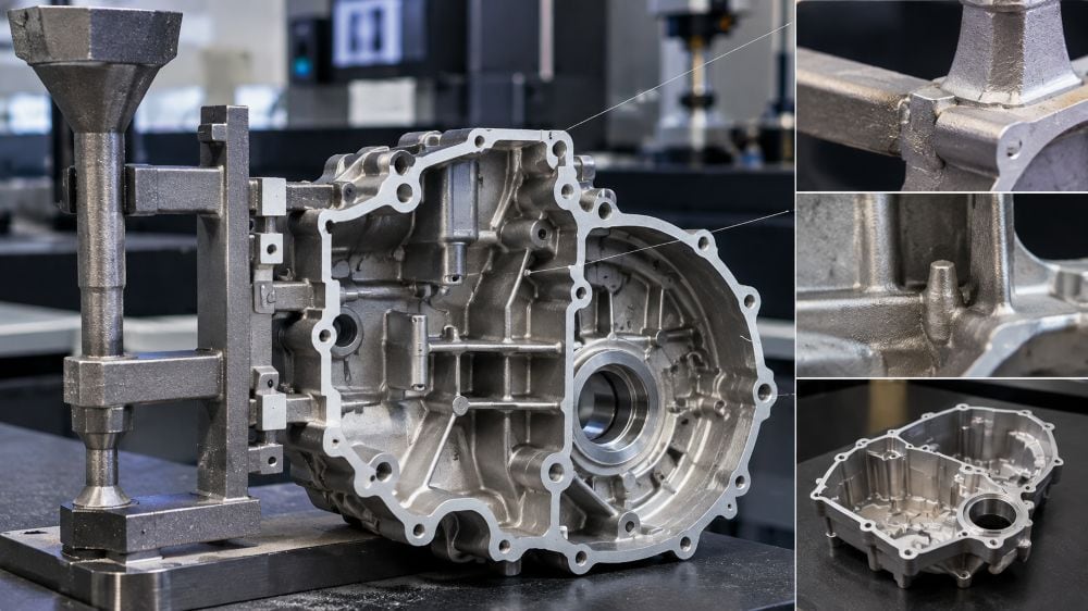
Ingate placement changes more than where metal enters a mold. It changes the temperature map, the path the metal takes, and the way the casting freezes. Put a gate in the wrong spot and a part can come up short at a thin end, overheat a sand core, or trap oxide where a later machining cut will find it. For a simple casting, the choice may be straightforward. Once the part has thick bosses, thin walls, cores, or pressure-tight areas, the gate location needs a real review.
This page focuses on that one decision: where the metal should enter the cavity. It is a useful companion to the broader casting engineering support from Miji, where runner layout, risers, mold design, alloy condition, and inspection are reviewed together.
The gate sets up the temperature pattern
The mold wall near an ingate sees a steady stream of hot metal. That area heats quickly. Areas farther from the entry point receive metal later and usually run cooler. Move the gate, and that pattern moves with it.
That is why gate placement is part of solidification control. It is not only a question of how fast the cavity fills. On a casting with a heavy section, a thin section, and a riser, the metal path should support the planned freezing direction. The riser has to stay connected to the section it is expected to feed.
In the shop, a bad layout often shows up as a familiar argument: the far end did not fill, so somebody wants to raise the pouring temperature. Sometimes that helps. Sometimes the far end is simply being asked to do too much after the metal has already crossed a long, cold path.
Start with the section map, not the easiest pattern cut
Before choosing a gate, mark the thick sections, thin sections, cores, risers, machining stock, sealing faces, and cosmetic surfaces. It takes a few minutes and avoids a lot of guesswork later.
For a broad casting with low height, the usual aim is to keep solidification reasonably even across the horizontal plane. Gates are commonly spread so metal reaches the casting without one side getting far ahead of the other. If the walls are mostly uniform, several entries around the perimeter can shorten the path to the last area to fill. Risers are then placed where the metal will remain hot longest.
When the wall thickness changes sharply, the plan usually needs more than extra gates. A thin wall may need to fill quickly, while a thick section may need a riser or local chill so it does not become an isolated hot spot. The answer depends on the part. A gate placed at a thick section can make sense, but not if it sends the first stream straight into a delicate core or a critical finished face.
Tall castings need a different fill direction
For a taller casting, the more reliable approach is often to let the metal rise from the lower portion of the cavity. This supports bottom-to-top solidification, with a top riser available to feed the last heavy area.
One bottom gate is not automatically enough. A tall, wide casting can still leave a long horizontal run on one side. Step gates or more than one entry level may be needed to keep a thin section from freezing before the metal reaches it. That is a design decision to prove with a trial or fill-and-solidification study, not an assumption to carry into tooling.
The important point is simple: decide where the casting should finish filling and where it should finish freezing. Those two locations should not be chosen by accident.
More gates can make the temperature field more even
The supplied reference compares a single ingate with four distributed ingates on a magnesium alloy component. With one concentrated entry, the temperature difference between the lower and upper measurement points was much larger after filling. With several entries distributed around the part, that difference was reduced.
That does not mean four gates are better than one on every casting. Every added gate brings more runner metal, trimming work, balance issues, and another location to inspect. Still, on a large plate or a thin-wall housing, one entry at an edge can leave the remote end waiting too long. A few well-placed gates may give the metal a shorter and calmer route.
For a cover-like casting, the usual red flag is easy to spot: metal enters from one side, runs the full length, and the last corner is also the thinnest area. That corner is where misruns and cold shuts tend to start. Distributed gates can shorten the fill distance, provided the flows meet in a controlled area rather than on a sealing face or a machined datum.
Do not shoot metal straight at a core or a wall
The flow direction at the ingate matters as much as the location. A stream that hits a round core, a raised boss, or a nearly vertical mold wall head-on can split, turn over, and entrain air. In sand casting, it can also overheat or erode a core.
The practical fix is often to turn the entry so the metal follows the contour instead of striking it. A gate facing a round core should direct the stream tangentially where geometry allows. On a long rectangular shell, metal is usually better introduced along the wall rather than straight into it. An inclined entry can also reduce the sharp swirl that occurs at the start of the fill.
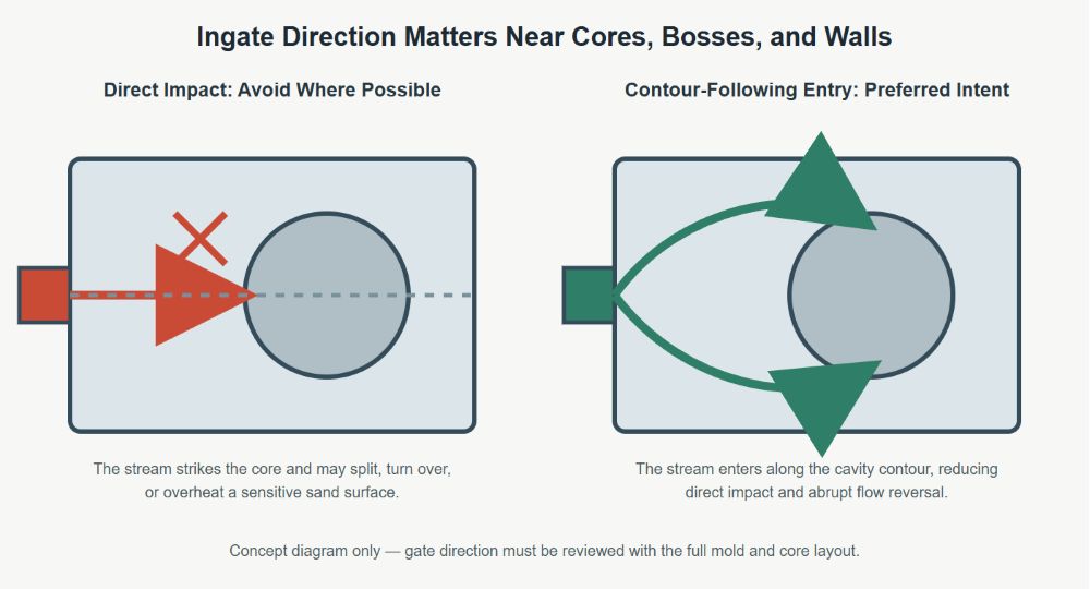
This is the sort of detail that looks minor on a 2D layout. It is not minor when the first pour hits the tool. A runner may be the correct size and still create a bad fill if the ingate aims the stream at the wrong feature.
A frame casting example: move the gate, calm the flow
The source material describes a sand-cast magnesium-alloy frame with a sand core through the middle. In the first arrangement, the metal entered from one side and had to pass over the top of the core before reaching the rest of the frame. The flow turned upward and downward, heated the core hard, and created conditions for gas and oxide-related defects in the upper area.
The revised arrangement moved the ingate to the other side. Metal entered the cavity more smoothly, the core saw less thermal shock, and the reported defects were removed in the trial.
The useful lesson is not that one side of every frame is the right side for a gate. It is that the metal path must be drawn through the actual cavity, including every core, bend, rib, and obstruction. A gate location that is close to a problem area may be the reason the problem exists.
Gate placement and riser placement have to agree
It is easy to review the gate and riser as separate features. They work as a system.
If a heavy section has a side riser, introducing metal through that same heavy area may support a useful feed path. If the gate sends the hottest metal somewhere else and the riser sits beyond a cold neck, the riser may not feed what the drawing expects it to feed. A thermal simulation is particularly useful when there are several thick sections or a complicated core package.
For a uniform wall casting, the source recommends gates distributed around the perimeter and risers placed at the regions that solidify last. For a tall casting, it recommends a rising fill with feeding from the top. These are good starting patterns, not drop-in layouts. The final design has to match the alloy, mold material, wall thickness, and mold orientation.
What to settle before releasing tooling
- Which area fills last, and can it stay hot long enough to fill?
- Which area freezes last, and how will it be fed?
- Does the ingate direct metal along a surface or straight into a core, wall, or boss?
- Where will separate metal fronts meet?
- Are the last-to-fill areas away from critical machining, sealing, and cosmetic surfaces?
- Can vents, overflow areas, and risers do their jobs without fighting the metal path?
If the team cannot trace the stream from the runner to the last thin section, it is too early to cut the pattern. A simple fill study, a wax layout, or a first-pour trial can answer questions that a clean CAD view hides.
A note for buyers and design teams
Send the foundry more than a part shape. Wall thickness, machining allowances, leak-test areas, cosmetic zones, required alloy, annual quantity, and inspection expectations all change the gate decision. The most useful quote review is one where the foundry can explain the intended metal path and show where the gates, risers, and vents will sit.
For the wider process discussion, see aluminum and magnesium alloy casting gating-system design. It covers runner behavior, gate-system types, venting, and light-alloy melt control.