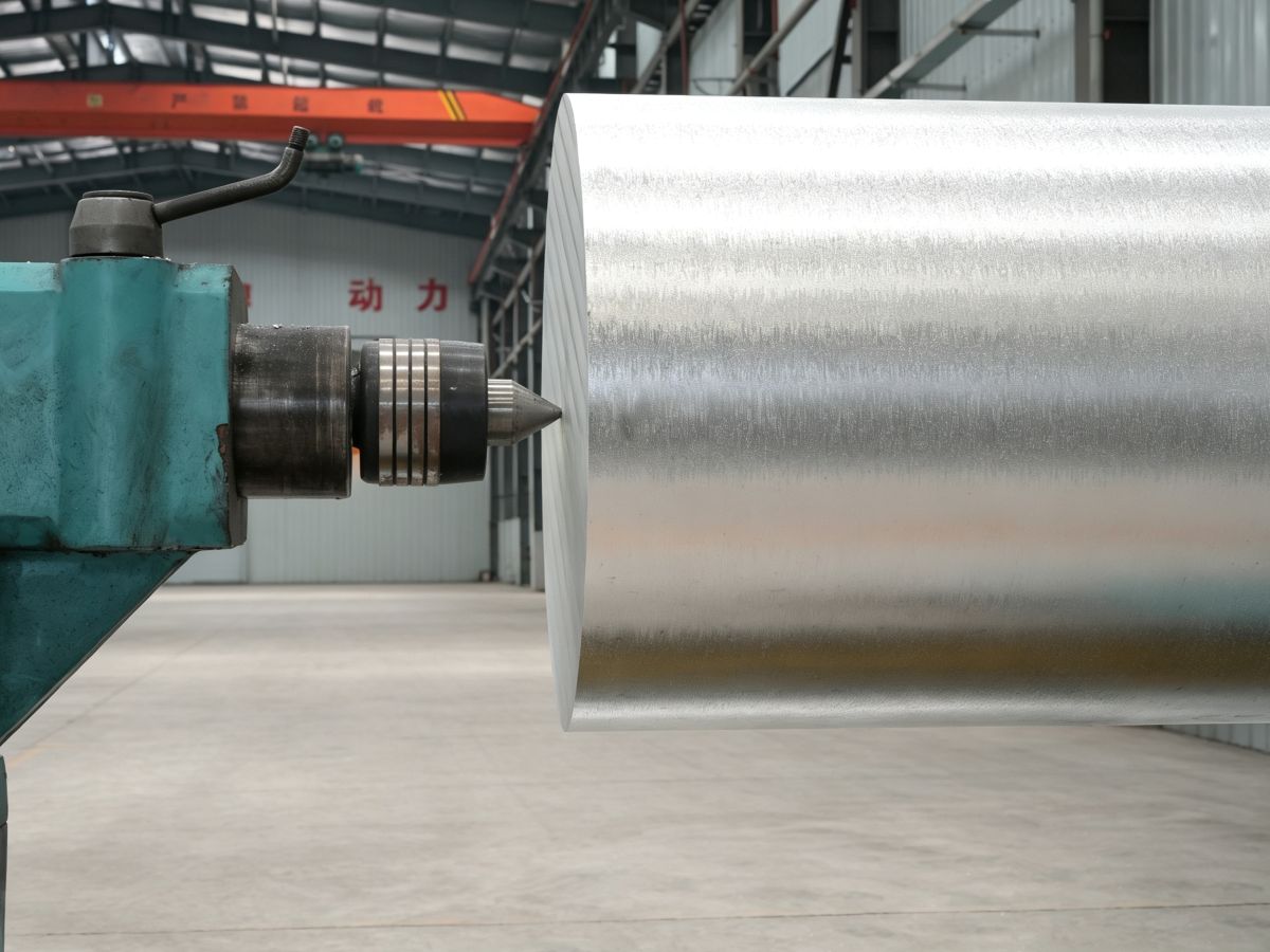
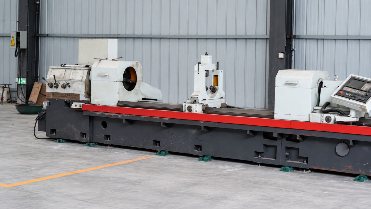
Magnesium alloys have low density, good thermal conductivity, and excellent machinability. Compared with many other structural metals, they can often be machined at higher cutting speeds with relatively low cutting forces. These characteristics support high productivity, long tool life, and good surface quality.
Successful Magnesium CNC Machining still requires suitable tool geometry, sharp cutting edges, effective chip removal, correct coolant selection, and careful control of heat and ignition risks. The following guidelines summarize the most important practices for machining magnesium alloy components.
Machining Characteristics of Magnesium Alloys
Magnesium alloys generally allow high cutting speeds, large depths of cut, and relatively high feed rates. Their good thermal conductivity helps cutting heat disperse rapidly through the workpiece. Cutting temperatures are therefore usually lower than those encountered when machining many other metals.
- Low cutting resistance and relatively low power consumption
- High permissible cutting speeds
- Good surface finish under suitable cutting conditions
- Long tool life when sharp tools are maintained
- Rapid heat dissipation through the workpiece
- A tendency to form discontinuous or partially broken chips
Chip formation depends on alloy composition, part geometry, material condition, tool geometry, and feed rate. Heavy cuts usually produce coarse, well-broken chips. Medium feeds tend to form shorter chips, while light feeds may produce longer, curved chips. Cast magnesium alloys are more likely to produce broken or partially fractured chips.
Thermal Expansion, Distortion, and Residual Stress
Magnesium alloys have a relatively high coefficient of linear thermal expansion. Within a temperature range of approximately 20–200°C, the coefficient is about 26.6–27.4 μm/(m·°C), depending on alloy composition.
Although heat normally dissipates quickly, high cutting speed combined with a heavy cut can still introduce significant heat into the part. This may cause dimensional variation or thermal expansion in close-tolerance components.
Cold-working stresses can also cause distortion. Rough machining may expose or redistribute these stresses near the surface. For precision parts, rough-machine the component while leaving approximately 0.5 mm of finishing allowance, allow it to stabilize when required, and finish-machine the remaining allowance in one or two light operations.
Stress-Relief Examples for Magnesium Alloys
| Alloy and condition | Example stress-relief treatment |
|---|---|
| AZ31B-F or AZ31B-O | 1–4 hours at 205°C |
| AZ31B-H24 | 1–4 hours at 135°C |
| AZ61A-F | 1–4 hours at 205°C |
| AZ80A-T5 | 1–4 hours at 205°C |
| ZK21A-F | 1–4 hours at 205°C |
| ZK60A-F | 1–4 hours at 205°C |
| ZK60A-T5 or T6 | 4 hours at 150°C |
Actual heat-treatment requirements should always be confirmed for the specific alloy, product form, and engineering specification.
Cutting Tools and Tool Geometry
Conventional carbon-steel tools can provide long service life when machining magnesium, but carbide-tipped tools are generally more economical for production work. Diamond tools may be used for magnesium-matrix composites or exceptionally fine finishes, although they are normally unnecessary for standard magnesium alloys.
Tools should have sharp, polished cutting edges, a large clearance angle, relatively few cutting edges, a moderate rake angle, and generous chip space. Regrind tools before they become completely dull, and avoid tools contaminated by previous machining of other metals.
Tool Sharpening
Cutting edges must remain free of nicks, burrs, rolled edges, chipping, and adhered material. Medium-grit wheels can be used for rough sharpening, followed by fine-grit wheels for accurate cutting geometry. Fine oilstone or ultra-fine oilstone may be used for hand honing.
A tool should be reground or replaced when it can no longer maintain tolerance, causes excessive heat, produces long chips with rough surfaces, or generates sparking near the cutting edge.
Dry Machining, Cutting Fluids, and Fire Safety
Magnesium is frequently machined without cutting fluid. Dry machining is clean and economical, but chips and dust must not be allowed to accumulate. Use chip guards, sloped trays, extraction, conveyors, or other chip-removal equipment appropriate to the production system.
Cutting fluid may be used to cool the workpiece, reduce distortion, extend tool life, and reduce ignition risk when fine chips are produced. Mineral-oil-based coolants are preferred. Animal and vegetable oils are unsuitable. The coolant should have relatively low viscosity, and its free-fatty-acid content should remain below approximately 0.2%.
Water-based systems require particular care because water can react with magnesium and release hydrogen. Ventilation, chip removal, monitoring, and safe handling of wet magnesium waste are essential.
Turning and Boring
For rough turning magnesium, a clearance angle of approximately 10–20° and a rake angle of approximately 10–15° are important. A zero-rake tool may be used for interrupted cutting and chip control, but it can increase surface roughness and energy consumption. For wide cuts or special contour turning, reducing the rake angle to approximately 3–8° can help prevent vibration.
| Operation | Cutting speed | Feed | Maximum depth of cut |
|---|---|---|---|
| Rough turning | 90–185 m/min | 0.76–2.5 mm/rev | 12.7 mm |
| Rough turning | 185–305 m/min | 0.51–2.0 mm/rev | 10.2 mm |
| Rough turning | 305–460 m/min | 0.25–1.5 mm/rev | 7.62 mm |
| Rough turning | 460–610 m/min | 0.25–1.0 mm/rev | 5.08 mm |
| Rough turning | 610–1,525 m/min | 0.25–0.76 mm/rev | 3.81 mm |
| Finish turning | 90–185 m/min | 0.13–0.64 mm/rev | 2.54 mm |
| Finish turning | 185–305 m/min | 0.13–0.51 mm/rev | 2.03 mm |
| Finish turning | 305–1,525 m/min | 0.076–0.38 mm/rev | 1.27 mm |
These are reference ranges rather than universal settings. Machine rigidity, tool material, alloy condition, wall thickness, clamping, and finish requirements must all be considered.
Drilling Magnesium
High-speed-steel twist drills can machine magnesium efficiently. For holes approximately 1.6–51 mm in diameter, reference feeds range from roughly 0.025 to 0.76 mm/rev.
- Use a sharp drill with polished flutes.
- Maintain effective chip evacuation.
- Use approximately a 118° point angle for general drilling.
- For deep holes, use a thick, uniform web and a margin about half the standard width.
- Provide a guide or pilot where necessary to prevent drill wander.
- Round the cutting-edge corners to improve surface finish and reduce burrs.
Deep-hole drilling requires particular attention when the depth-to-diameter ratio exceeds approximately 20:1. For thin-sheet production, reducing the point angle to approximately 60°, using a cross-cutting angle of approximately 120–135°, thinning the web, and applying a light helix can reduce wander, thrust variation, and burrs.
Reaming and Counterboring
Magnesium reamers should provide generous chip space. Straight or spiral flutes may be used, generally with four to six flutes. Typical geometry includes a 45° lead chamfer, approximately 7° rake, a 0.15–0.30 mm land, 5–8° primary relief, and approximately 20° secondary relief.
Leave at least 0.25 mm reaming allowance on diameter; approximately 0.38 mm is often preferred. High-speed-steel reamers commonly operate at approximately 30–120 m/min, while carbide-tipped reamers may reach approximately 260 m/min where equipment permits. Feed generally ranges from approximately 0.13 to 0.76 mm/rev.
Flat-bottom counterboring tools should have a narrow cutting land of approximately 0.38 mm, together with adequate clearance and relief. Reference maximum speeds are approximately 195 m/min for high-speed-steel tools and 490 m/min for carbide tools.
Tapping Magnesium
Standard taps may be used for small batches, while dedicated magnesium taps are preferred for high production or close-tolerance threads. High-speed-steel taps are generally suitable; carbide taps are rarely required.
- Use straight or spiral flutes.
- Limit flute-land width to about 30% of the tap circumference.
- Use two flutes below approximately 4.8 mm diameter.
- Use three flutes below approximately 19 mm diameter.
- Use two flutes above approximately 19 mm diameter.
- Use approximately 3–5° root rake where better chip removal is required.
Milling Magnesium
Magnesium milling cutters can often use only one-half to one-third as many teeth as cutters used for other metals. Fewer teeth create more chip space, reduce rubbing and power demand, and permit higher cutting speeds.
Typical cutter geometry includes approximately 10° relief, a 1.6 mm land width, and approximately 20° auxiliary relief. Magnesium can generally be milled at the maximum spindle speed, feed, and depth permitted by a rigid machine and suitable tool.
| Operation and tool | Roughing speed | Roughing feed | Finishing speed | Finishing feed |
|---|---|---|---|---|
| Face milling, HSS cutter | 275 m/min | 0.90 mm/tooth | 460 m/min | 0.36 mm/tooth |
| Face milling, carbide cutter | Machine maximum | Machine maximum | Machine maximum | 0.30 mm/tooth |
| Peripheral milling, HSS cutter | 275 m/min | 0.90 mm/tooth | 395 m/min | 0.41 mm/tooth |
Sawing and Grinding
Magnesium can be cut with hand saws, power saws, band saws, and circular saws. Blades should have large gullets, sufficient tooth relief, and accurate alignment. Reference peripheral-speed limits include approximately 610 m/min for high-speed-steel circular blades and up to approximately 3,000 m/min for carbide-tipped blades under suitable conditions.
Grinding is rarely necessary because conventional machining can produce a good finish. Where grinding is required, standard tooling may produce approximately 0.25–0.75 μm surface roughness. Fine magnesium dust is hazardous, so extraction, housekeeping, suitable wheel selection, and fire prevention are essential.
Practical Magnesium Machining Checklist
- Confirm the alloy, temper, product form, and required tolerance.
- Use a sharp, polished tool with generous chip space.
- Select adequate clearance without weakening the cutting edge.
- Use a rigid machine and clamp the workpiece without distortion.
- Start with proven reference parameters and adjust for the machine.
- Maintain continuous chip removal.
- Prevent chips and dust from accumulating.
- Use suitable mineral-oil coolant where cooling or fire control is required.
- Provide ventilation if a water-based system is used.
- Monitor heat, vibration, tool wear, surface finish, and chip condition.
Conclusion
Magnesium alloys are among the most machinable structural metals. High cutting speeds, low cutting forces, and good heat conduction make them suitable for efficient turning, drilling, milling, tapping, sawing, and other precision operations.
The best results depend on sharp tools, correct geometry, generous chip clearance, rigid equipment, reliable chip extraction, and disciplined fire-safety procedures. Reference cutting parameters should always be adjusted for the actual alloy, machine capability, tool material, component geometry, and required tolerance.
Technical note: The numerical values in this article are reference ranges translated and reorganized from the supplied technical pages. They should be validated through controlled machining trials and applicable engineering standards before production use.