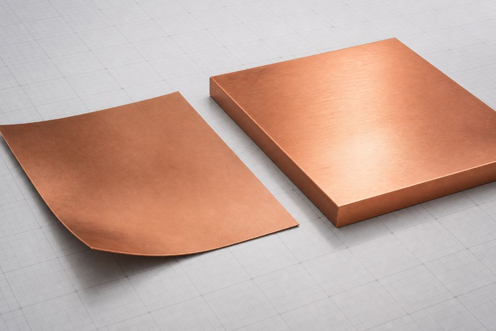
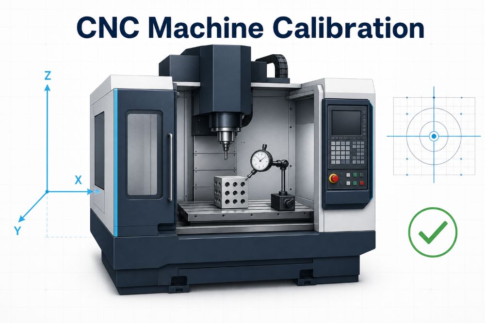
Fixture design affects CNC part accuracy long before the first cutter touches the material. A machine can be well calibrated and the program can be correct, but the finished part will still move if it is located poorly, clamped unevenly, or left unsupported under cutting load.
Good workholding does two jobs at once. It places the part in a repeatable position, and it keeps the part stable without bending it. That balance is especially important for thin walls, open pockets, long plates, soft materials, and tight-tolerance features.
Why Fixture Design Matters in CNC Machining
A fixture controls the relationship between the workpiece and the machine. It establishes where the part sits, which surfaces are referenced, how the part resists cutting force, and whether the same setup can be repeated across a batch.
Without a stable fixture, a part can shift during machining or spring back after the clamps are released. The machine may produce a feature in the right place relative to the distorted part, but the released part can still be wrong.
Fixture quality is therefore part of the process capability. It supports the same goal as CNC machine calibration: removing uncontrolled motion before it becomes a dimensional error.
Location and Clamping Are Not the Same Thing
Location tells the part where to sit. Clamping holds the part against the locators. These jobs should not be confused.
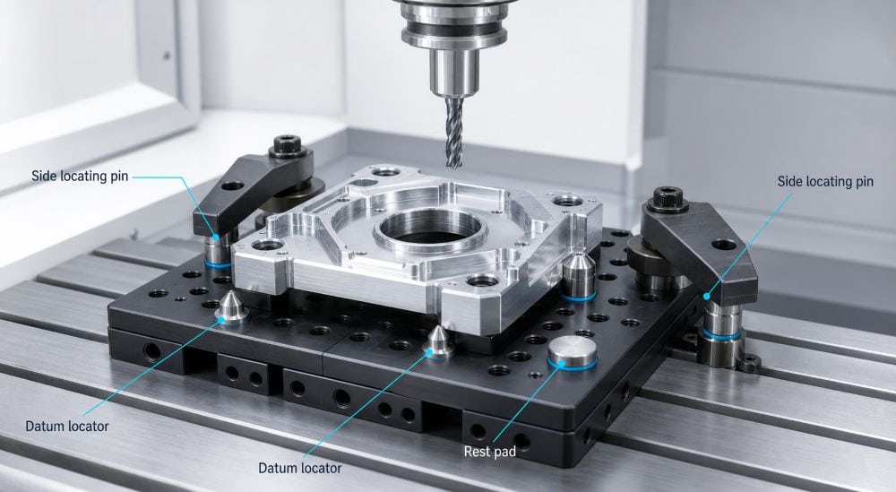
Locators can be rest pads, pins, shoulders, nests, or machined fixture faces. They establish the part’s datum relationship. Clamps apply force so the part stays seated during machining. A clamp should press the part into a stable location, not act as the only thing defining position.
When clamps are used as locators, results often change from one operator or setup to the next. When the locating scheme is clear, clamping can be lighter, more repeatable, and less likely to distort the part.
The 3-2-1 Principle, Explained Simply
The 3-2-1 principle is a common way to think about fixture location. Three points support the primary datum plane. Two points locate a second face. One point stops movement in the last direction.
The point is not to copy the exact count on every part. The point is to remove the six directions of movement without over-constraining the workpiece. A part needs enough location to repeat; too many hard contacts can fight each other when stock variation or thermal movement is present.
| Fixture element | Basic job | Common mistake |
|---|---|---|
| Primary rest pads | Support the main datum plane | Supporting only the edges of a thin part |
| Side locators or pins | Set lateral position | Using a clamp face as a locator |
| End stop | Controls final linear position | Leaving no allowance for stock variation |
| Clamps | Keep the part seated | Adding force where support is missing |
| Secondary supports | Resist local cutting load | Setting them too high and lifting the part |
For a close-tolerance part, the fixture datum scheme should agree with the drawing datum scheme whenever practical. That makes setup, programming, and inspection speak the same language.
Support Matters as Much as Clamp Force
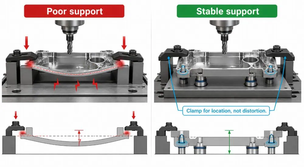
Many accuracy problems come from unsupported material, not weak clamps. A wide pocket, a thin floor, or a long rail may flex when the cutter passes over it. Tightening the clamps harder can make the issue worse because the part is bent before machining starts.
Support should be placed near expected cutting loads and critical features. Rest pads, jacks, contoured nests, and sacrificial backing can reduce deflection. They should support the part without changing the datum position.
Thin parts often need a process plan as well as a fixture. A roughing pass can release stress. A finishing pass may need lighter cuts, more support, or a different clamp sequence. The answer is rarely “just tighten it more.”
How Clamping Force Creates Distortion
Every clamp adds load to the workpiece. A stiff block may barely notice. A thin aluminum cover, copper plate, magnesium housing, or long stainless part may bend under the same force.
The difficult cases are often the ones that look flat while clamped. The cutter creates a good feature. The clamps are released. The part relaxes and a face becomes bowed, a bore moves, or the part no longer sits flat on an inspection surface.
Use the lowest practical force that keeps the part seated against its locators during cutting. Spread the load with appropriate clamp pads. Avoid clamping directly over a thin unsupported area. If strong clamping is truly required, revisit the support and machining sequence first.
Datum Strategy: Start From the Functional Surfaces
The best fixture does not begin with the easiest place to clamp. It begins with the surfaces that matter in the finished assembly.
If a face seals, locates, mates to another component, or controls a critical bore position, it is a strong candidate for the fixture and inspection datum strategy. If a rough outside edge disappears later in the process, it may be a poor reference choice.
This connection matters because CNC machining tolerances are not only size limits. They also depend on the relationship between features. A good datum plan keeps those relationships controlled from setup through final inspection.
Common Fixture Errors and Their Symptoms
| What you see on the part | Possible fixture issue | First action |
|---|---|---|
| Size changes after unclamping | Clamp distortion or poor support | Measure clamped and free-state condition; review support |
| Hole position varies by setup | Unclear or worn locators | Check datum contact points and pin condition |
| Wall taper or inconsistent pocket size | Part movement or tool deflection | Verify seating, clamp sequence, tool reach, and cutting load |
| Flatness fails after machining | Edge-only support or stress release | Add controlled support and revise rough/finish sequence |
| Burrs and vibration near a feature | Weak local support | Support near the cutting zone or reduce cutting load |
Do not assume every variation is a fixture problem. Tool wear, machine geometry, temperature, programming, and material variation also matter. A useful diagnosis compares parts across the batch and checks when the trend began.
Fixture Design for Thin-Wall and Lightweight Parts
Thin-wall parts are where fixture decisions become visible. Aluminum, magnesium, copper, and thin stainless components can all distort from clamping or cutting force, even when the machine is performing correctly.
Start by supporting the broadest stable area. Use rest pads or a shaped nest where the part can tolerate contact. Keep clamps away from thin open walls when possible. Use light finishing cuts and avoid leaving a weak wall unsupported until the last operation.
Material response also changes with temperature. A part may move while it is warm, then measure differently after cooling. The effect is not only a machine problem; it is part of the whole workholding and inspection plan. See how temperature affects CNC accuracy for the measurement side of this issue.
Prototype Fixtures vs. Production Fixtures
Prototype work often uses soft jaws, modular plates, vises, or simple custom blocks. That is usually the right tradeoff when the design may still change. The focus is quick setup, safe access, and enough control to validate the part.
Production work may justify a dedicated nest, hydraulic or pneumatic clamping, repeatable locating pins, loading aids, and in-process checking. The fixture cost is higher, but it can reduce setup time, variation, operator dependence, and inspection burden over a large run.
| Production situation | Practical fixture approach |
|---|---|
| One-off or early prototype | Modular workholding, soft jaws, simple stops |
| Small repeat batch | Reusable baseplate with documented locators and supports |
| Repeated production | Dedicated fixture with repeatable load/unload method |
| Tight-tolerance feature | Datum-controlled fixture plus defined inspection plan |
| Thin or fragile part | Broad support, controlled clamp force, light finishing strategy |
How to Verify Fixture Performance
Verify a fixture with the part, not just with an empty setup. Check that the workpiece seats on the intended datums. Confirm clamp force and contact points. Machine a first article, then inspect the features that the fixture is meant to protect.
For recurring work, record setup notes, support positions, clamp sequence, work offset method, and first-piece results. If a dimension starts moving over a batch, compare the fixture condition with the tool and offset history. This avoids changing the wrong variable.
In close-tolerance work, fixture verification belongs inside the precision CNC machining process, not as an afterthought when a part fails inspection.
Buyer Checklist Before Requesting a CNC Quote
- Provide a drawing with clear functional datums.
- Identify faces that seal, locate, or must remain flat.
- State the critical tolerances and inspection requirements.
- Tell the supplier if the part is thin, open, flexible, or cosmetic.
- Include material, temper, finish, quantity, and assembly context.
- Ask whether a dedicated fixture is needed for the run size.
These details help the supplier choose a workable fixture route before machining starts. For a drawing review, request a machining review.
Frequently Asked Questions
How does fixture design affect CNC accuracy?
It controls how the part is located, supported, and held against cutting loads. A poor fixture can let a part move or bend, creating errors even when the program and machine are correct.
Can clamping a part too tightly cause errors?
Yes. Strong clamps can distort thin or flexible material. The part may look correct while held, then spring back after unclamping and fail flatness, position, or size checks.
What is the 3-2-1 principle in fixture design?
It is a location concept that uses three points for the main plane, two for a second direction, and one for the last direction. It helps control position without over-constraining the part.
Should the fixture datum match the drawing datum?
Whenever practical, yes. Matching them helps keep machining and inspection aligned with the function of the part.
What is the best fixture for thin-wall parts?
There is no single answer. Good designs usually use broad support, light balanced clamps, tool access, and a rough/finish sequence that avoids leaving weak areas unsupported.
Does a calibrated CNC machine eliminate fixture errors?
No. Calibration controls machine-motion error. A part can still shift, distort, or relax because of poor location, support, or clamping.
Final Takeaway
Fixture design is a direct part of CNC accuracy. Locate the part from functional datums, support it where cutting forces act, and use clamp force to hold—not to reshape. Those basics reduce rework and make a machining process easier to repeat.