CNC machine calibration checks whether a machine can position and move its axes within the accuracy needed for production. A machine may repeat the same motion well while still carrying a geometric, positioning, or thermal error that changes the finished part.
Calibration goes beyond one good component. It measures machine behavior, helps identify error sources, and supports mechanical adjustment or controlled compensation before a batch develops dimensional problems. This article explains common CNC calibration methods as industry practice. It does not claim that Miji owns or uses every instrument described below.
What Is CNC Machine Calibration?
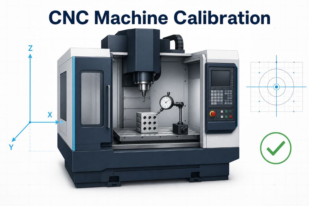
CNC machine calibration is the process of measuring actual machine motion against a known reference. The check may cover linear positioning, repeatability, squareness, spindle runout, circular interpolation, or multi-axis behavior.
It is not one single test. A dial indicator can answer a quick question at the machine. A ballbar can show how two axes behave together in a circle. A laser interferometer can measure linear positioning over travel. Each method sees a different part of the problem.
The goal is practical: keep the machine’s error small enough, understood enough, and controlled enough for the work it is being asked to do.
Calibration vs. Verification vs. Maintenance
These terms are related, but they are not interchangeable.
Calibration measures a machine or instrument against a traceable reference and establishes error. Verification confirms whether the process can meet a specific production need. Maintenance restores or protects machine condition through cleaning, lubrication, alignment, repair, and adjustment.
A test cut can verify a real part. It does not prove the full geometric condition of the machine. A laser measurement can characterize a linear axis. It does not replace routine maintenance. Good shops use the right tool for the question in front of them.
Why CNC Machines Lose Accuracy
Accuracy changes over time because machines are mechanical systems. Ballscrews, guideways, bearings, couplings, seals, and fixtures all age. A crash or heavy interrupted cut can change a condition quickly. Slow wear can change it gradually.
Common contributors include backlash, lost motion, worn guideways, loose couplings, spindle runout, thermal growth, contaminated reference surfaces, and a machine that has been moved or leveled poorly. The part can also be the source of the problem if it is unstable under clamping or changes temperature during machining.
For a clearer explanation of the result versus the process, see accuracy, precision and repeatability.
Signs That a CNC Machine Needs Calibration
Watch for a repeated pattern, not one isolated reject. A stable part that starts drifting in one direction, circular pockets that are not round, holes that move after a program has been proven, or changed squareness between faces can all be useful signals.
Other signs include rising correction values, inconsistent first-off parts, an unusual difference between positions in the work envelope, new chatter, or a change after a crash, relocation, or spindle repair.
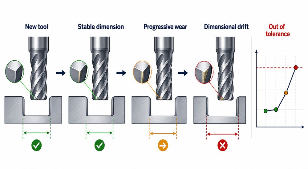
Tool wear, workholding, measurement method, and temperature can create similar symptoms. Start with the simple checks. Confirm the tool, the fixture, and the measuring method before assuming the machine needs a full calibration.
Common CNC Calibration Methods
| Method | What it can check | Best use | Main limitation |
|---|---|---|---|
| Dial indicator | Runout, simple axis movement, backlash clues | Daily or setup-level checks | Does not prove full spatial accuracy |
| Test cut | Actual machined result | Production validation | Does not isolate the root cause easily |
| Granite square | Squareness of motion or setup | Basic geometric checks | Limited coverage of the work volume |
| Ballbar test | Circular interpolation, servo and geometric behavior | Periodic machine health check | Does not cover every volumetric error |
| Laser interferometer | Linear positioning and repeatability | Precision calibration work | Needs specialist equipment and environmental control |
| Probe or reference sphere | In-machine checks and multi-axis verification | Production verification | Still depends on machine motion and probe condition |
No method is automatically “best.” A quick dial-indicator check may be all that is needed after a setup change. A machine supporting close-tolerance production may need a more formal accuracy study.
Test Cuts and Reference Parts
Test cuts are direct and useful because they reveal what the machine, tooling, program, and fixture produce together. A simple reference part can check bore size, face squareness, pocket geometry, circularity, and position relationships.
The limitation is diagnosis. If a test part fails, the machine may be responsible, but so may the cutter, toolholder, fixture, program, material, or inspection setup. Use a test cut as a production check, then narrow down the cause with targeted measurements.
For a new or critical job, a controlled first article and documented reference dimensions often give purchasing and engineering more useful information than a vague statement that the machine is “accurate.”
Ballbar Testing
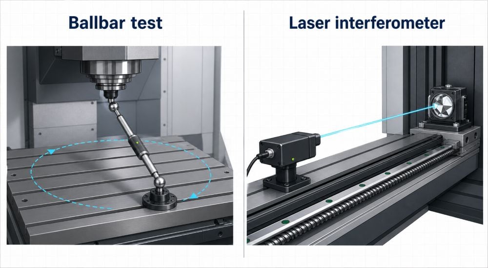
A ballbar test uses a precision telescoping bar between a fixed ball and a machine-mounted ball. The machine follows a circular path while the instrument records changes in bar length.
The pattern can help identify issues such as backlash, servo mismatch, stick-slip, reversal spikes, squareness error, or a scale mismatch between axes. It is a strong periodic health check for circular interpolation behavior.
It is not a full proof of three-dimensional machine accuracy. Think of it as a diagnostic snapshot: fast, useful, and best interpreted alongside the machine history and the type of parts being produced.
Laser Interferometer Calibration
Laser interferometer calibration measures linear axis travel against a highly accurate optical reference. It can reveal positioning error, repeatability, backlash, and compensation needs along an axis.
This method is commonly used for formal calibration or when close-tolerance work requires a detailed linear-axis check. It needs careful setup. Air temperature, pressure, humidity, vibration, alignment, and warm-up condition can affect the result.
Laser work is often performed by a qualified external calibration provider when a shop does not maintain the equipment in-house. It is important to state that clearly in supplier communication rather than implying capability that has not been verified.
How Often Should a CNC Machine Be Checked?
There is no honest one-size-fits-all interval. The right schedule depends on machine age, workload, material, tolerance risk, crash history, environment, and the consequences of a bad part.
As a practical starting point, use quick checks at setup or after unusual events; use planned process verification for recurring work; and use formal calibration based on the machine’s service plan, customer requirements, or a demonstrated change in capability.
The tighter the CNC machining tolerances on a functional feature, the shorter and more documented the check interval should be. This is not about checking everything constantly. It is about controlling the risks that matter.
What to Do After a Crash, Relocation, or Repair
Do not return straight to close-tolerance work after a crash, machine move, major axis repair, spindle replacement, or foundation change. Start with a visual and mechanical review. Check toolholder and spindle runout, probe condition, home return, fixture location, level, and obvious axis behavior.
Then run an appropriate verification plan. That may include an indicator check, reference part, ballbar test, or external calibration. The scope should match the event. A minor tool collision is different from a machine that has been transported across a facility.
Keep the record. The value is not only in finding an issue; it is also in showing when the machine condition changed.
How Calibration Supports Part Tolerances
Machine calibration does not replace sound programming, sharp tools, stable workholding, or inspection. It supports all of them by reducing unknown motion error.
A well-calibrated machine can still make a bad part if a thin wall moves under clamping. A good fixture can still produce a bad bore if the spindle has runout. The process has to be treated as a system.
Temperature is part of that system. Long parts and light alloys can move between machining and inspection. See how temperature affects CNC accuracy when close dimensions are affected by heat.
The practical payoff is clearer process capability. It helps a supplier decide whether a feature can be machined directly, needs a different setup, needs finishing, or needs a tolerance review before production.
Practical Accuracy Verification Checklist
- Confirm the correct drawing revision, datums, and critical features.
- Check spindle and toolholder condition.
- Verify workholding location and clamp repeatability.
- Warm up the machine when the process requires it.
- Check a reference feature or first-off part before the full run.
- Compare measurements at consistent temperatures.
- Review offset history instead of making unexplained changes.
- Escalate sudden changes after a crash, repair, or relocation.
- Use the calibration method that matches the risk, not the most impressive instrument name.
For projects that need a documented process plan, the precision CNC machining process is the right starting point.
Frequently Asked Questions
What is CNC machine calibration?
It is the measurement and adjustment or compensation of machine motion against known references. It helps confirm that the machine can position and move accurately enough for the intended work.
How do you calibrate a CNC machine?
The method depends on the error being checked. Shops may use indicators, reference parts, granite squares, ballbar tests, probes, or laser interferometers. The right sequence starts with the problem you are trying to verify.
Is a ballbar test the same as laser calibration?
No. A ballbar evaluates circular interpolation and can reveal several servo or geometric patterns. A laser interferometer measures linear-axis positioning with much greater detail. They complement each other.
Can a test cut prove CNC accuracy?
It proves the result of one process under one setup. That is valuable, but it cannot by itself separate machine error from tooling, fixture, programming, material, or measurement error.
How often should CNC accuracy be verified?
Use the machine condition, part tolerance, usage level, and service history to set the interval. Check sooner after a crash, relocation, repair, or unexpected dimensional trend.
Does calibration eliminate all machining error?
No. It controls machine-motion error. Tool wear, fixture distortion, thermal movement, material variation, and inspection method still need their own controls.
Final Takeaway
CNC machine calibration is a process-control tool, not a marketing label. Measure the right behavior, use a method that fits the risk, document the result, and verify the actual part. That is how calibration supports reliable production. For a part and tolerance review, request a machining review.