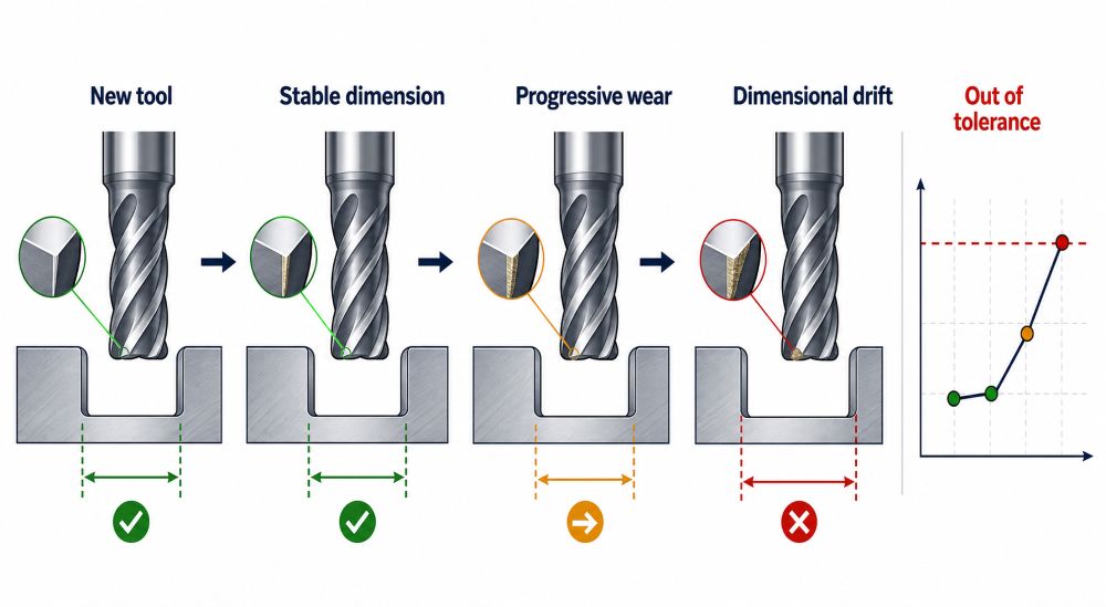
Tool wear can push a CNC process out of tolerance even when the machine, program, and fixture have not changed. As the cutting edge wears, its effective geometry changes. Cutting force goes up. Dimensions can slowly move away from target.
In plain terms, this is how tool wear affects machining accuracy: the programmed path stays the same while the cutting edge no longer removes material in the same way.
That does not always look like a broken tool. The first parts may pass. Later parts may show dimensional error, rougher surfaces, burrs, or an unstable hole or slot size. Tool wear control matters whenever a batch must hold repeatable CNC machining tolerances.
What Is Tool Wear in CNC Machining?
Tool wear is the gradual loss or change of the cutting edge during machining. It can occur on the flank behind the edge, on the rake face where chips slide, or at one concentrated point on the tool.
The important point is simple: a tool does not need to fail visibly before it becomes a quality risk. It may still cut metal, but no longer cut it consistently enough for the drawing.
For that reason, a practical CNC tool-life limit should be based on part quality and process stability, not only on whether the insert or end mill is still usable. The right replacement point is before the process reaches a functional tolerance limit.
How Tool Wear Changes CNC Part Dimensions
Wear changes the tool that actually touches the part. That can change the finished size even though the program value has not moved.
In CNC milling, end-mill wear can affect slot width, pocket size, outside profiles, wall taper, and floor finish. A worn cutting edge also creates more cutting force. On a thin wall or a long tool reach, that extra force can increase deflection.
In CNC turning, wear at the tool nose or flank can change outside diameters, bores, tapers, cylindrical form, and surface finish. The direction of the size change is not universal. It depends on the operation, compensation direction, tool geometry, and how the control is set up.
Common Types of CNC Cutting Tool Wear
Not every edge problem has the same cause or needs the same response. Built-up edge, for example, is not traditional material loss, but it changes the effective cutting edge and can cause the same kind of unstable result.
| Wear type | Typical sign | Effect on the part | Likely contributor |
|---|---|---|---|
| Flank wear | A polished wear land behind the edge | Gradual dimensional drift and higher cutting force | Normal use, excessive speed, abrasive material |
| Crater wear | A depression on the rake face | Weaker edge and changed cutting geometry | Heat and chip flow |
| Notch wear | Local wear at the depth-of-cut line | Burrs, poor finish, local size variation | Work-hardened surface or scale |
| Built-up edge | Workpiece material stuck to the edge | Unstable size and torn surface | Adhesion or unsuitable parameters |
| Edge chipping | Small fractures on the edge | Sudden size or finish change | Vibration or interrupted cutting |
| Thermal cracking | Fine cracks on an insert | Short, unpredictable tool life | Repeated heating and cooling |
Signs That Tool Wear Is Affecting Accuracy
The clearest signal is a consistent trend. If a critical bore, shaft, slot, or wall dimension moves in one direction through a batch, tool wear should be on the check list.
Other signs include more frequent wear-offset edits, changing surface marks, growing burrs, higher spindle load, changed cutting sound, vibration, and a shift in chip color or shape. A tool with unpredictable life can also make identical lots behave differently.
Still, do not blame every out-of-tolerance part on the cutter. Fixture movement, thermal expansion, work-coordinate error, material stress, and inconsistent inspection can create similar symptoms. Diagnose the pattern before changing an offset.
Tool Wear vs. Thermal Drift vs. Fixture Error
This quick comparison helps a team start in the right place.
| Symptom | More likely cause | Check first |
|---|---|---|
| Slow, one-direction size drift | Tool wear or machine warm-up | Tool history, offsets, and part temperature |
| Sudden size jump | Edge chipping or fixture movement | Cutting edge, clamps, and work offset |
| Size changes after the part cools | Thermal movement | Machining and inspection temperature |
| Difference after every re-clamp | Datum or fixture repeatability | Locators, datum faces, and clamp sequence |
| Poor finish and size change together | Tool wear or vibration | Edge condition, runout, and cutting load |
Temperature deserves special attention with close fits, long parts, and light alloys. Learn more about how temperature affects CNC accuracy before treating a warm measurement as a final result.
How Tool Wear Affects Surface Finish
A part can remain within dimensional tolerance while its surface finish has already become unacceptable.
As a cutting edge loses sharpness, it may rub and drag rather than cut cleanly. Friction and heat increase. Built-up edge can pull at the material. The result can be unstable tool marks, tearing, chatter, and larger burrs.
This is why surface finish is an early warning signal, not just a cosmetic item. A finish change on a noncritical face may be harmless. The same change on a sealing surface, bearing seat, or sliding component can be a functional issue.
The supplied magnesium-alloy machining reference makes the same practical point: sharp tools, clean cutting action, controlled chips, and suitable cutting conditions matter. Magnesium may machine easily, but a dull edge can still create heat, burrs, and dimensional instability.
How CNC Shops Monitor Tool Wear
The best monitoring method depends on the part, quantity, and tolerance risk. A prototype does not need the same control plan as a repeated production program.
| Production situation | Practical wear control |
|---|---|
| Prototype | Inspect critical features after machining and check the edge visually |
| Small batch | First-article inspection plus scheduled dimensional checks |
| Repeated batch | Tool-life record, offset history, and documented replacement limits |
| High-volume production | SPC trends, in-process probing, and controlled tool replacement |
| Tight-tolerance feature | Short inspection interval and a defined action limit before the tolerance edge |
Simple controls are often effective: visual inspection, part counts, tool-life timers, and first-piece checks. For more demanding work, shops may add spindle-load monitoring, vibration sensing, machine probes, tool setters, and statistical process control.
The goal is not to add technology for its own sake. It is to catch a predictable drift before it becomes scrap.
When Should Tool Wear Offsets Be Used?
Wear offsets are useful for small, predictable changes supported by real measurements. They are not a substitute for finding the cause of a large or sudden error.
For example, a turned diameter may trend gradually toward the upper tolerance limit. If inspection confirms a small, repeatable shift, a controlled wear-offset adjustment may restore the target. The change should be recorded and kept inside a defined compensation limit.
Do not use an offset to hide a chipped edge, loose fixture, thermal shift, bad datum, or programming error. If the offset correction suddenly grows, or needs frequent changes, stop and inspect the tool and setup. A worn cutter should be replaced before compensation becomes a rescue plan.
For context on the controls behind this approach, see our precision CNC machining process.
How to Prevent Tool Wear From Causing Out-of-Tolerance Parts
- Match tool grade, coating, and geometry to the workpiece.
- Use suitable speed, feed, and depth of cut for the feature.
- Control toolholder condition and tool runout.
- Keep workholding stable without distorting the part.
- Monitor critical dimensions during the batch.
- Record offset changes rather than making undocumented edits.
- Set tool-life and replacement limits from actual process data.
- Inspect the edge after abnormal load, vibration, or sound.
- Measure parts under consistent temperature conditions.
- Separate slow drift from sudden process changes.
The inspection interval should follow the feature’s functional limit and the agreed CNC machining tolerances. A cosmetic edge and a locating bore should not receive the same control plan.
Practical Production Example
Illustrative example — not a published customer case: A shop is milling a light-alloy housing with a narrow locating slot. The slot has a functional width requirement, while the outside profile is less critical.
Early parts measure close to target. After repeated cycles, the slot begins to trend toward one limit and the finish on the wall becomes less even. The team first checks the fixture and measurement method. Both are stable. Inspection then finds flank wear and material build-up at the cutter edge.
The corrective action is to replace the cutter, reset the verified offset, and shorten the inspection interval for that slot. The team also records the number of completed parts at replacement. On later batches, that record becomes a practical tool-life limit.
The lesson is not “replace every tool early.” It is to use the part’s critical feature as the decision point. That is where a tool-life rule creates real value.
Frequently Asked Questions
Can tool wear cause CNC parts to go out of tolerance?
Yes. Wear can change the effective edge geometry, increase force, and move a dimension over time. The first parts may pass while later parts drift toward or beyond the limit.
How does tool wear affect dimensional accuracy?
It can change slot widths, profiles, diameters, bores, taper, and form. The direction of change depends on the tool, operation, control compensation, and how the part is held.
What are the first signs of CNC tool wear?
Look for a repeatable size trend, worsening finish, more burrs, rising load, changed cutting sound, vibration, or frequent offset adjustments. Confirm with a tool and setup inspection.
Does tool wear always make a dimension larger?
No. A worn tool does not create one universal direction of error. Measure the actual feature and check the tool, compensation direction, and process before making an adjustment.
How are CNC wear offsets used?
They correct a small, measured, predictable drift. They should have documented limits and should never be used to conceal sudden damage, fixture movement, or a program problem.
When should a CNC cutting tool be replaced?
Replace it before part quality or process stability reaches the action limit. A reliable rule can use measured trend data, finish requirements, tool inspection, and a planned part count.
Can a worn tool still produce acceptable parts?
Sometimes, but that does not make it safe for a tight-tolerance production run. A tool can still remove material after it has stopped producing consistent results.
Final Takeaway
Tool wear is a normal part of CNC machining. Uncontrolled wear is not. Track the critical dimensions, inspect the edge, use wear offsets carefully, and replace the tool before the process reaches the tolerance limit. For a drawing or process review, request a manufacturability review.