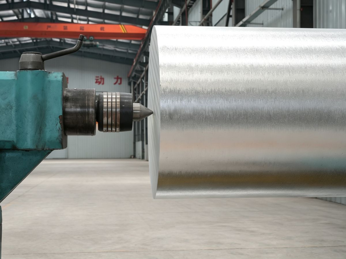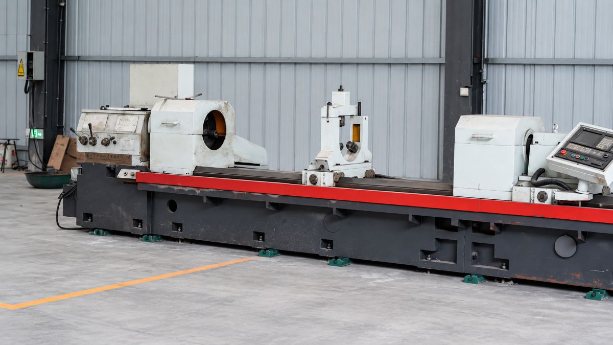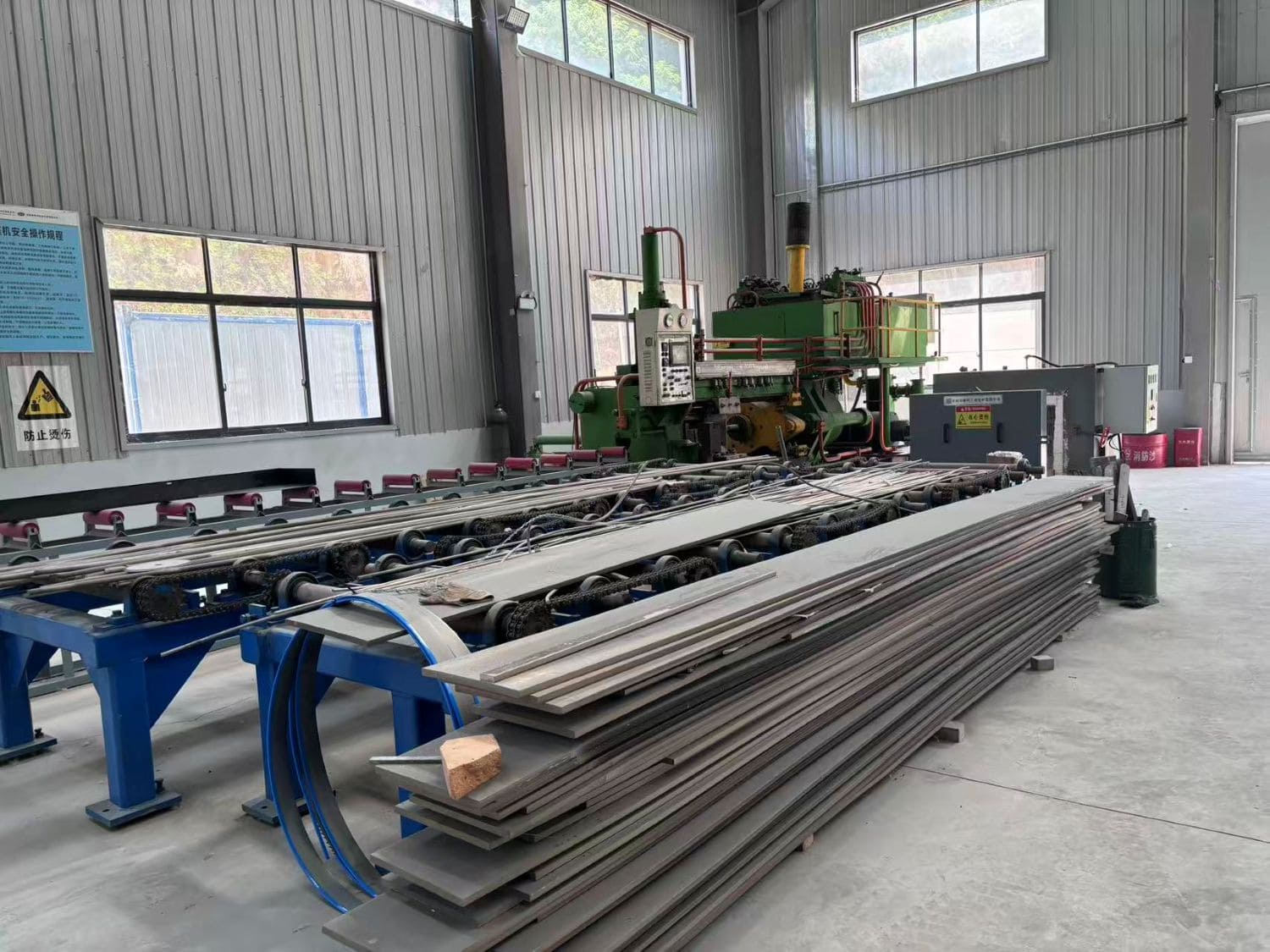
CNC parts rarely fail because the machine forgot how to cut. They fail because the workpiece moved, flexed, vibrated, or was clocked from the wrong datum before the tool even touched it. That is the quiet truth behind most tolerance issues. The blueprint, the toolpath, and the stock all look perfect—yet you still end up with a warped wall, a shifted bore, or a surface mark you can’t explain to the customer.
Workholding isn’t a side detail; it is the foundation of machining accuracy. A rigid spindle cannot save an unsupported part, a sharp cutter cannot fix a flawed staging strategy, and a beautiful CAD model means nothing if your clamps distort the material. Good fixturing is the sole difference between a lucky prototype and stable, repeatable production.
The Bottom Line: CNC workholding is the art of locating, supporting, and securing a part. It dampens vibration, preserves datum integrity, prevents deformation, and ensures maximum tool access without damaging the component.
1. What Is CNC Workholding?
CNC workholding is more than just cranking down a vise. At its core, it answers three fundamental questions: where does the part sit, how is it clamped, and how does it stay rigid against heavy cutting forces?
A proper workholding setup is an engineered system of locators, reference datums, support blocks, custom jaws, fixture plates, and pins. Sometimes it even involves vacuum or magnetic chucks. The goal isn’t to crush the material into submission. It is about securing the workpiece firmly at the exact coordinates, maximizing tool access, and maintaining total stability throughout the cut.
1.1 Workholding Has Three Jobs
- Locate the part: The fixture must define the part position based on reliable datum surfaces.
- Hold the part: The fixture must resist cutting forces without allowing lift, sliding, or rotation.
- Protect the part: The fixture must avoid clamp marks, distortion, vibration, and surface damage.
2. Why Workholding Matters More Than Buyers Often Realize
When a buyer sends a drawing for quotation, the conversation often starts with material, tolerance, quantity, surface finish, and lead time. Those are important. But if the part has thin walls, deep pockets, long unsupported sections, intersecting holes, or multiple machining setups, workholding becomes just as important as the machine itself.
A fixture mistake can create problems that look like machining problems. Chatter may be blamed on the cutter. A shifted hole may be blamed on programming. A warped plate may be blamed on material quality. In many real cases, the root cause is simpler: the part was not supported or located correctly.
2.1 Typical Symptoms of Weak Workholding
- Hole positions drift between batches.
- Flat surfaces become slightly bowed after unclamping.
- Thin walls spring back after machining.
- Chatter marks appear in one area but not another.
- Parts pass inspection in the fixture but fail after release.
- Surface finish changes because the part vibrates under load.
These are not small details. For industrial components, they affect assembly fit, sealing, bearing alignment, thermal contact, electrical contact, and long-term reliability.
3. The Engineering Principles Behind Good CNC Workholding
3.1 Locate Before You Clamp
A good machinist thinks about location before force. The part must sit against known reference surfaces before any clamp pressure is applied. If the part is floating, tilted, or resting on burrs, clamping only locks the error in place.
This is why datum planning matters. The best datum is not always the largest face. It is the surface that best represents how the part will function in the final assembly. For a housing, that may be a sealing face. For a bracket, it may be a mounting surface. For a shaft-related component, it may be a bore or axis.
3.2 Support the Part Where Cutting Forces Enter
Cutting force does not ask permission. It pushes the part in the direction the cutter is working. If that force is directed into air, the part bends. If it is directed into a weak clamp area, the part vibrates. If it is directed into a well-supported locator, the cut becomes stable.
A practical workholding plan should consider where the tool enters, where the force travels, and where the part needs backing. This is especially important for long plates, thin ribs, magnesium housings, copper conductive components, and lightweight structural parts.
3.3 Avoid Over-Clamping
More clamp force is not automatically better. Over-clamping can bend thin walls, distort bores, close slots, flatten soft materials, or create residual stress. The problem is often hidden during machining because the part looks stable while it is still clamped. Once released, it moves.
That delayed movement is one of the most frustrating CNC problems. The machine did exactly what it was told to do, but it cut a part that was already elastically deformed.
3.4 Keep Tool Access in the Plan
A fixture that holds the part perfectly but blocks the cutter is not a good fixture. Clamp position, tool approach, spindle clearance, drill access, probe access, and chip evacuation all need to be considered before programming begins.
This is why experienced suppliers do not separate fixture planning from process planning. The fixture and the toolpath must work together.
4. Common CNC Workholding Methods
There is no single best workholding method. There is only the method that fits the part, material, tolerance, and production goal.
| Workholding Method | Best For | Main Advantage | Common Risk |
|---|---|---|---|
| Standard vise | Simple blocks, plates, and rigid parts | Fast setup and strong grip | Can distort thin or soft parts |
| Soft jaws | Irregular shapes and repeatable profiles | Better contact and lower marking risk | Requires careful jaw machining |
| Modular fixture | Small-batch industrial parts | Flexible and reusable | Less optimized than dedicated tooling |
| Dedicated fixture | Repeat production and critical parts | High repeatability and process stability | Needs upfront planning |
| Vacuum workholding | Thin flat plates and delicate surfaces | Even support with low surface damage | Limited resistance to heavy cutting |
| Custom machined nest | Complex housings and cast or forged parts | Supports difficult geometry | Must match real part variation |
4.1 Vises and Mechanical Clamps
Mechanical workholding is the shop-floor standard for many parts. It is direct, rigid, and easy to adjust. A vise works well when the part has strong parallel faces and can tolerate jaw pressure.
The mistake is using a standard vise for every part. Thin-wall components, soft materials, and irregular castings often need something more thoughtful. If the jaws only touch a small area, the part may tilt or compress. If the clamp point is too far from the cutting area, vibration can appear.
4.2 Soft Jaws
Soft jaws are often the first step toward better workholding. They can be machined to match the part profile, spread contact over a larger area, and reduce clamp marks. They are especially useful for repeat jobs where the same geometry appears again and again.
Soft jaws are not magic. They still need a clean datum plan. If the jaw shape is wrong or the part is loaded inconsistently, repeatability will suffer.
4.3 Modular Fixtures
Modular fixtures are useful when a shop handles many different parts in small or medium batches. They allow pins, clamps, stops, and supports to be repositioned without building a new dedicated fixture every time.
Their strength is flexibility. Their weakness is that they may not be as rigid or as fast as a dedicated fixture. For prototype and low-volume production, that tradeoff is often acceptable.
4.4 Dedicated Fixtures
A dedicated fixture is built for one part or one part family. It is usually the right direction when repeatability, speed, and dimensional consistency matter more than flexibility.
Dedicated fixtures are common for recurring industrial components, housings, brackets, frames, and parts that must be machined from several sides. They can reduce operator variation and make inspection results more predictable.
4.5 Vacuum and Low-Pressure Holding
Vacuum workholding is useful for thin, flat, or surface-sensitive parts. Instead of pushing down on a few points, it supports a larger area. This can reduce distortion and surface marking.
However, vacuum holding is not suitable for every cut. Heavy side loads, deep roughing, small contact areas, or porous materials can make vacuum unreliable. In those cases, vacuum may support the part while mechanical stops resist lateral force.
5. How to Choose the Right Workholding Method
The right fixture is chosen by the part, not by habit. A good supplier should look at the drawing and ask how the part will behave during machining.
5.1 Start With the Geometry
- Does the part have flat and reliable datum surfaces?
- Are there thin walls, ribs, slots, or long unsupported sections?
- Will the part need machining from multiple sides?
- Are there surfaces that cannot be marked?
- Will clamps interfere with holes, pockets, or contour cutting?
5.2 Match the Fixture to the Material
Material behavior changes the fixture strategy. Magnesium alloy cuts easily but needs attention to chip handling, thermal expansion, and safe machining practice. Copper is soft and can mark or smear if clamped poorly. Aluminum is generally friendly but still moves when thin. Rigid plastics may creep, compress, or warp under heat and clamp force.
| Material Type | Workholding Concern | Practical Fixture Approach |
|---|---|---|
| Magnesium alloy | Low cutting force, but safety and chip control matter | Use stable support, sharp tools, clean chip evacuation, and avoid unnecessary friction |
| Copper | Soft surface, burr tendency, possible marking | Use soft contact, controlled clamp force, and clean support surfaces |
| Aluminum | Good machinability but thin sections can move | Use soft jaws, step machining, and support near thin walls |
| Rigid plastics | Compression, heat movement, and stress release | Use broad support, lighter clamping, and controlled cutting heat |
| Cast or forged blanks | Surface variation and uneven stock | Use custom nests, adjustable locators, and rough-to-finish sequencing |
5.3 Think About Inspection Before Cutting
Good workholding should make inspection easier. If the drawing has critical hole patterns, sealing faces, or alignment surfaces, the fixture should support those inspection priorities. The supplier should understand which dimensions matter most in assembly, not only which ones are hardest to machine.
6. Common CNC Workholding Problems and How to Avoid Them
6.1 Part Lift
Part lift happens when cutting force pulls or pushes the workpiece away from its seat. It can create taper, uneven depth, or inconsistent hole position.
How to prevent it: place clamps so force pushes the part into its locator, use stops against lateral load, and confirm the part is fully seated before machining.
6.2 Thin-Wall Distortion
Thin walls are easy to machine badly. Clamp too hard and the wall bends. Clamp too lightly and the wall vibrates. Cut too aggressively and the wall springs away from the tool.
How to prevent it: use soft jaws, temporary support, staged roughing and finishing, reduced unsupported length, and final light passes after stress has been released.
6.3 Datum Error Between Setups
Many parts fail when they are flipped, rotated, or re-clamped. Each setup creates a chance for small location errors. These errors show up as misaligned holes, mismatched faces, or poor concentricity.
How to prevent it: machine reliable datums early, use dowel pins or machined stops, inspect after re-clamping, and avoid changing datum logic halfway through the process.
6.4 Clamp Marks and Surface Damage
Some parts are dimensionally correct but visually unacceptable. Copper, aluminum, magnesium, and finished surfaces can show marks if contact pressure is concentrated in the wrong area.
How to prevent it: use soft pads, machined soft jaws, protected contact surfaces, and avoid clamping on cosmetic or sealing areas.
6.5 Chatter From Poor Support
Chatter is not always a tooling issue. If the part is hanging out too far from the fixture, the cutter and workpiece start arguing. The result is noise, vibration, poor finish, and reduced tool life.
How to prevent it: reduce overhang, support close to the cutting zone, choose the cutting sequence around stiffness, and leave enough material during roughing to keep the part stable.
7. Workholding Best Practices for Precision CNC Machining
7.1 Plan the Fixture Before CAM
The fixture should not be an afterthought. If the CAM path is created before the workholding plan, the machinist may later discover that clamps block the tool, datums are inaccessible, or the part cannot be held safely.
A better sequence is simple: review the drawing, define functional datums, decide setup order, plan support, then program the toolpath.
7.2 Use Roughing and Finishing Strategically
For parts that may move, do not try to finish everything in one aggressive pass. Remove material in stages. Let stress release. Keep the part supported. Then finish critical features after the geometry is stable.
This matters for magnesium alloy plates, lightweight housings, thin brackets, and precision components where flatness and alignment matter after unclamping.
7.3 Keep Contact Surfaces Clean
A chip under the part can ruin a datum. A burr on a locating face can tilt the workpiece. A dirty jaw can create false clamping. Many fixture errors are not complicated. They come from small debris in the wrong place.
Good shops clean locators, inspect contact points, deburr intermediate surfaces, and avoid loading parts on rough stock faces when precision matters.
7.4 Control Clamp Force
Experienced machinists do not simply tighten until it feels safe. They understand that every material has a different response to pressure. Consistent clamp force improves repeatability, especially in batch production.
For sensitive parts, torque-controlled clamps, hydraulic clamping, soft jaws, or distributed support can reduce variation between operators.
7.5 Design Parts With Workholding in Mind
Designers can make CNC machining easier by leaving enough stock for clamping, adding temporary tabs, providing accessible datum surfaces, avoiding impossible undercuts, and considering how the part will be held during each setup.
A small design adjustment made before production can save a large amount of fixture trouble later.
9. Why Miji Looks at Material and Machining Together
For industrial components, material selection and CNC workholding should not be separated. Magnesium alloy, copper, aluminum, and engineering plastics each behave differently under clamp force, cutting heat, and tool pressure. A fixture that works for one material may create problems in another.
At Miji Magnesium, the stronger approach is to connect material form, machining strategy, and application requirements early. If a part will be machined from magnesium plate, extruded profile, forged blank, or cast stock, the supplier should understand how the material route affects support, stability, and final dimensional behavior.
This is especially important when lightweight components must also meet structural, thermal, electrical, or assembly requirements. The goal is not only to make a part. The goal is to make a part that stays correct after it leaves the machine.
Need Help With CNC Machined Magnesium or Industrial Components?
If your project involves magnesium alloy parts, copper components, lightweight housings, thin-wall structures, or custom CNC machining requirements, Miji Magnesium can help review material form, machining risk, and fixture-related concerns before production starts.
Contact Miji Magnesium to discuss your material and CNC machining requirements.