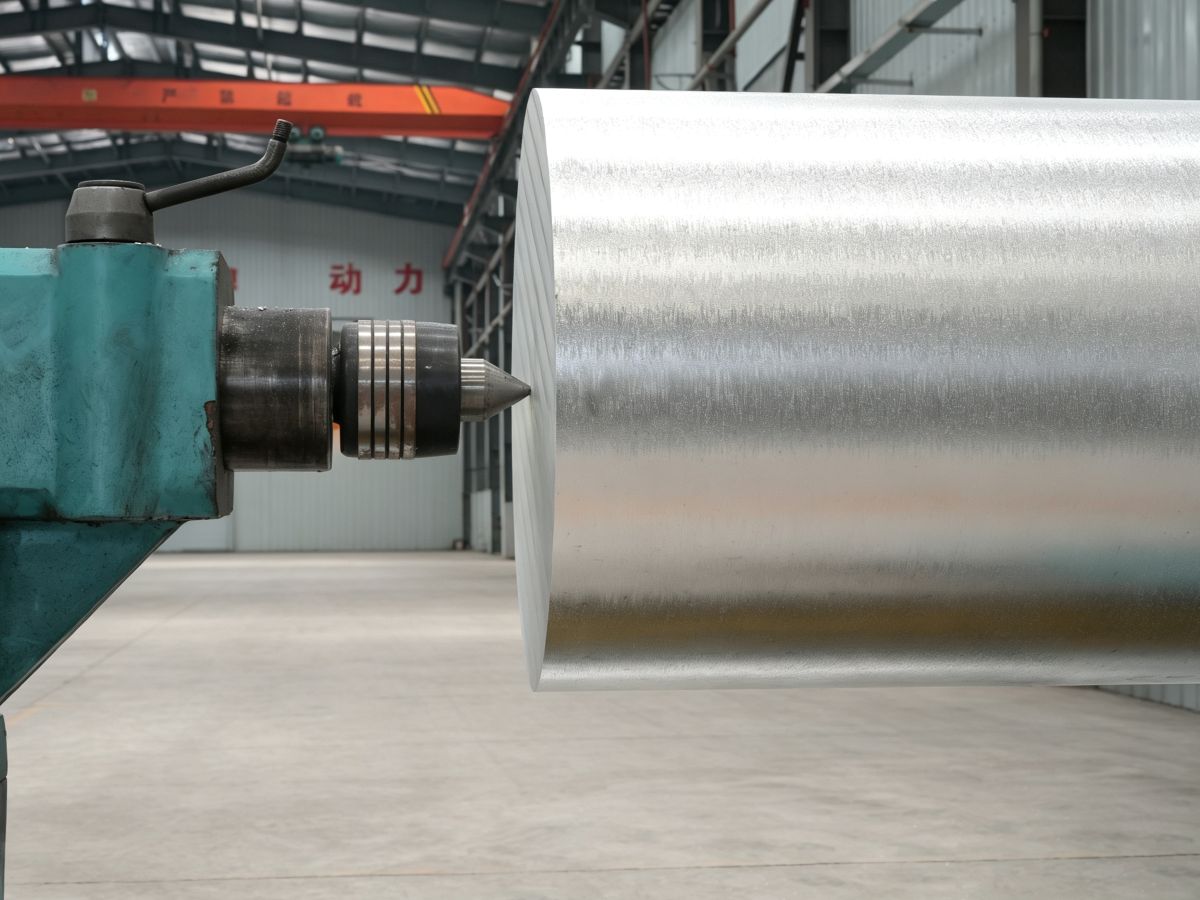
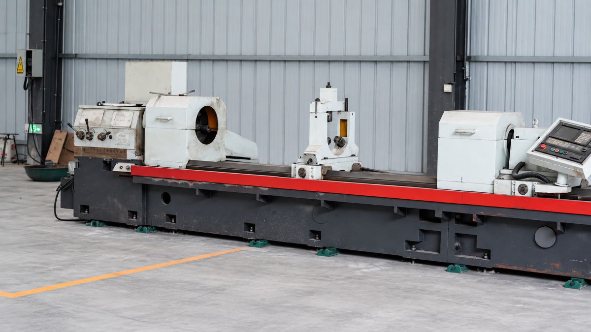
A CNC machined part can be dimensionally correct and still fail the moment it reaches assembly. The hole fits, the profile checks, the tolerance report looks clean, but the sealing face leaks, the coating peels, the edge feels sharp, or the visible surface looks uneven under shop light. That is why surface finish is not a cosmetic afterthought. In real manufacturing, it is often the quiet difference between a part that simply passes inspection and a part that performs confidently in the field.
Direct Answer: CNC machining surface finish is the controlled texture left on a part after cutting, turning, milling, drilling, grinding, or secondary finishing. It affects sealing, friction, coating adhesion, corrosion resistance, fatigue behavior, assembly feel, and customer perception. A better finish does not come from one parameter alone. It comes from the right material condition, sharp tooling, stable workholding, controlled chip evacuation, suitable cutting strategy, proper deburring, and clear drawing requirements.
This article is part of Miji Magnesium’s CNC content cluster. For a broader foundation on process types, materials, tolerances, and sourcing logic, read the complete CNC machining guide.
1. What CNC Machining Surface Finish Really Means
Surface finish is the final texture, pattern, and condition of a machined surface. It includes roughness, tool marks, burrs, waviness, direction of machining lines, and sometimes the condition after deburring, polishing, coating, anodizing, or cleaning.
1.1 Surface Finish Is Not the Same as “Looks Smooth”
A surface may look clean but still perform poorly if it has directional tool marks across a sealing face. Another surface may look slightly matte but work perfectly because its roughness, flatness, and lay match the application. In industrial CNC machining, visual appearance is only one part of the story.
For example, a decorative cover may need a uniform visible surface. A gasket face needs controlled sealing behavior. A sliding surface needs friction control. A coating-ready surface needs proper adhesion. A threaded hole needs burr-free entry and clean engagement. These are different finishing goals.
1.2 The Best Finish Is the Right Finish
One common mistake is assuming that smoother is always better. It is not. A very smooth surface may reduce friction in one application, but it may also reduce coating grip in another. A slightly textured surface may be better for bonding, painting, or conversion coating. The real question is not “How smooth can you make it?” The better question is “What does this surface need to do after machining?”
2. Why Surface Finish Affects Part Performance
Surface finish sits at the meeting point between design intent and real-world use. When it is controlled well, the part feels better, assembles better, wears more predictably, and supports downstream treatment more reliably.
2.1 Sealing and Contact Surfaces
Sealing faces, gasket lands, O-ring grooves, and mating surfaces are sensitive to peaks, valleys, scratches, and directional tool paths. A surface may meet a dimensional tolerance but still leak if the machining pattern creates a pathway across the sealing zone.
2.2 Friction, Sliding, and Wear
Moving components need controlled surface texture. Too rough, and wear accelerates. Too smooth, and lubrication behavior may not match the design. The surface must support the contact condition, not just look attractive.
2.3 Coating and Surface Treatment
For magnesium alloy, aluminum, copper, and other metals, surface finish can influence cleaning, coating adhesion, conversion treatment, anodizing response, and paint quality. A surface with embedded chips, smeared material, or uneven polishing can create finishing problems later.
2.4 Corrosion and Environmental Durability
Surface condition also affects corrosion behavior. Scratches, burrs, crevices, trapped contaminants, and inconsistent finishing can become weak points, especially in humid, salt, or industrial environments. This is especially important for magnesium alloy components because surface protection and assembly design often matter as much as the base alloy itself.
3. What Controls Surface Finish During CNC Machining
Surface finish is not created by one machine setting. It is the result of the whole process. A strong CNC supplier looks at the full chain before promising a finish.
3.1 Material Condition
The same geometry can machine differently depending on whether the stock is plate, extrusion, forging, casting, or heat-treated material. Internal stress, grain direction, hardness variation, and inclusions can all affect surface quality.
3.2 Tool Sharpness and Tool Geometry
Dull tools create heat, tearing, burrs, and inconsistent marks. Sharp tools cut cleaner and reduce the chance of smearing or built-up edge. Tool geometry matters even more when machining softer metals, thin walls, copper alloys, magnesium alloys, and engineering plastics.
3.3 Workholding Stability
If the part moves, vibrates, or relaxes after unclamping, surface finish will suffer. Thin-wall parts, lightweight housings, and large flat plates often need careful fixture planning. A good finish cannot be forced onto an unstable setup.
3.4 Chip Control
Chips that recut against the surface can leave scratches, dents, or embedded marks. This is a common problem in deep pockets, narrow slots, blind holes, and lightweight metal parts where chip evacuation is not planned well.
3.5 Cutting Strategy
Toolpath direction, step-over, feed strategy, finishing passes, cutter engagement, and entry/exit movement all influence the final surface. A rushed roughing strategy may save time early but create more work during finishing and inspection.
4. CNC Process Types and Surface Finish Risk
| CNC Process | Surface Finish Strength | Common Finish Risk | Buyer Question to Ask |
|---|---|---|---|
| CNC Milling | Good for flat faces, pockets, housings, brackets, and complex features | Tool marks, chatter, step-over lines, burrs at edges | Which surfaces need finishing passes? |
| CNC Turning | Strong for round parts, shafts, bushings, and cylindrical surfaces | Feed marks, poor parting finish, chatter on slender parts | Is the surface functional, cosmetic, or both? |
| Drilling | Efficient for holes and fastener features | Burrs, poor entry or exit finish, chip packing | Are burr-free holes required? |
| Tapping and Threading | Creates functional fastening surfaces | Torn threads, burrs, poor thread start, chip blockage | Is thread inspection required after deburring? |
| Grinding or Polishing | Useful for tighter finish or appearance requirements | Over-polishing, rounding edges, inconsistent cosmetic direction | Should the finish be measured before or after secondary treatment? |
5. How Material Choice Changes Surface Finish Strategy
No serious CNC surface finish guide should ignore material behavior. The cutter does not care what the drawing wishes. It responds to the metal in front of it.
5.1 Magnesium Alloy Parts
Magnesium alloys often machine cleanly because they have low cutting resistance and good machinability. That can support efficient cutting and attractive surface quality. But magnesium machining also requires disciplined chip handling, sharp tools, proper heat control, and responsible process planning. Fine chips and dust should not be treated casually.
For magnesium housings, plates, lightweight brackets, and precision components, surface finish should be considered together with corrosion protection, coating, deburring, and assembly design. You can learn more from Miji Magnesium’s magnesium alloy CNC machining page.
5.2 Copper and Copper Alloy Parts
Copper conducts heat and electricity well, but it can be more difficult to finish cleanly because it may smear, grab, or form built-up edge if the tooling and cutting strategy are not suitable. Conductive copper components often need clean contact surfaces, controlled burrs, and careful handling to avoid dents or surface contamination.
5.3 Aluminum Parts
Aluminum is widely machined and can deliver excellent surface finish, but different alloys respond differently. Some cut cleanly, while others may create built-up edge or cosmetic inconsistency. If the part will be anodized, painted, or brushed, finish planning should begin before machining.
5.4 Stainless Steel and Harder Metals
Harder metals create more cutting heat and tool wear. Surface finish problems often come from vibration, work hardening, tool deflection, or poor coolant strategy. These materials require a more conservative approach than lightweight alloys.
5.5 Rigid Plastics
Rigid plastics may look easy to machine, but they can deflect, melt, chip, or show stress marks if the setup is wrong. Surface finish depends heavily on cutter sharpness, heat control, fixture support, and chip evacuation.
6. How to Specify CNC Surface Finish on a Drawing
The best RFQs do not ask for a perfect finish everywhere. They tell the supplier which surfaces matter and why. This helps control quality without adding unnecessary manufacturing burden.
Practical Rule: Specify surface finish by function. Do not treat hidden clearance faces, sealing faces, cosmetic faces, sliding surfaces, coating surfaces, and electrical contact areas as if they need the same finish.
6.1 Mark Critical Surfaces Clearly
Identify sealing faces, bearing seats, electrical contact areas, coating-critical zones, visible cosmetic faces, and friction surfaces. These are the areas where finish requirements carry real value.
6.2 Define Burr Expectations
“Deburr all edges” is not always enough. If the part has fluid channels, sealing grooves, threaded holes, or electrical contact surfaces, specify where burrs are unacceptable and whether sharp edges must be broken in a controlled way.
6.3 State Finish Before or After Treatment
If the part will be anodized, plated, painted, conversion coated, polished, or blasted, clarify whether the roughness requirement applies before or after the surface treatment. This avoids confusion during inspection.
6.4 Avoid Over-Specifying Non-Functional Areas
Requiring a fine finish on every face may increase production difficulty without improving performance. A better drawing separates critical and non-critical surfaces.
| Surface Type | Finish Priority | Common Requirement |
|---|---|---|
| Sealing face | Very high | Controlled roughness, lay direction, flatness, and burr-free edges |
| Cosmetic visible face | High | Uniform tool marks, no scratches, consistent appearance |
| Internal pocket | Medium | Clean machining, no loose burrs, functional clearance |
| Threaded hole | High | Clean thread start, controlled burr, proper engagement |
| Coating surface | High | Clean surface, no contamination, treatment-ready texture |
| Hidden clearance face | Low to medium | Functionally acceptable finish without unnecessary polishing |
7. Common Surface Finish Problems and What They Usually Mean
7.1 Chatter Marks
Chatter usually points to vibration. The cause may be weak workholding, long tool overhang, aggressive cutting, poor machine rigidity, or unstable part geometry. Chatter is not only visual. It can affect fatigue, sealing, and customer confidence.
7.2 Smearing
Smearing is common in softer or ductile materials when the cutter rubs instead of cutting cleanly. It may appear on copper, some aluminum alloys, and plastics. Sharp tooling and correct cutting conditions are essential.
7.3 Burrs at Edges and Holes
Burrs are more than an appearance issue. They can interfere with assembly, sealing, coating, fastening, and safe handling. Burr control should be planned during machining, not only fixed afterward.
7.4 Scratches and Recut Chips
Scratches often come from chip recutting, poor cleaning, rough handling, or inadequate packaging. If the finish is cosmetic or coating-critical, handling and storage must be part of the quality plan.
7.5 Uneven Finish Between Surfaces
This can happen when a part requires multiple setups, different toolpaths, or mixed machining directions. For visible components, finish direction should be discussed before production.
8. Inspection: How Surface Finish Should Be Verified
Good inspection is not just measuring a number. It means checking whether the surface meets its real purpose. A professional supplier may combine several inspection methods depending on the part.
- Visual inspection: Useful for scratches, stains, tool marks, dents, and cosmetic uniformity.
- Tactile inspection: Helpful for burrs, sharp edges, and obvious roughness problems.
- Roughness measurement: Used when Ra, Rz, or other roughness values are specified.
- Functional inspection: Important for sealing faces, sliding areas, contact surfaces, and coated parts.
- Sample approval: Valuable when cosmetic appearance or texture direction matters.
For repeat production, a first article sample or approved reference part can prevent arguments later. It gives the buyer and supplier a shared definition of acceptable finish.
9. Why Supplier Experience Matters
Surface finish is one of those areas where a low-quality supplier may say yes too quickly. A better supplier asks questions first. Which face seals? Which face is visible? Is the part coated? Is the finish measured before or after treatment? Will the part be assembled with another metal? Will there be sliding, vibration, heat, or corrosion exposure?
At Miji Magnesium, the focus is not only on making parts lighter or machining them to size. For magnesium alloy, copper, and precision industrial components, the real value is helping customers align material form, CNC strategy, surface finish, and downstream treatment. That is how a machined part becomes more than a cut block of metal. It becomes a component that is easier to assemble, easier to protect, and easier to trust.
Need CNC Parts with Controlled Surface Finish?
If your project involves magnesium alloy housings, copper conductive components, lightweight brackets, plates, prototypes, or production parts, Miji Magnesium can help review the drawing, material route, machining strategy, and surface finish requirements before production risk becomes expensive rework.
Contact Miji Magnesium to discuss your CNC machining project.