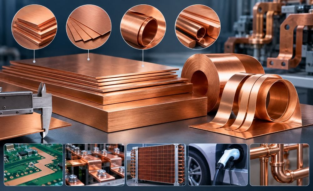
C110 is an excellent electrical conductor, but it does not always make a cooperative machining chip. It is soft, ductile, and happy to smear when the tool is dull, rubbing, or short on clearance. That is why a C110 drawing needs more than a material note and a handful of tight dimensions. Before releasing the part, an engineer should decide what the stock really is, which faces do the real work, where the part can be held, and what an acceptable edge looks like after machining.
Before the drawing leaves your desk
Most C110 problems are not mysterious. They show up as ordinary shop-floor issues: stringy chips wrap around a cutter; a thin copper plate looks flat until the vise opens; a drilled hole leaves a sharp whisker on the back side; a “critical” surface turns out to be cosmetic after all.
Take ten minutes to check the drawing for five things: the full material callout, the condition of the stock, the functional dimensions, the way the part will be held, and the edges that cannot be altered. That small review is usually more valuable than adding another blanket tolerance note.
C110 is not the answer to every copper question
C11000 is a solid choice for busbars, grounding parts, conductive plates, terminals, and many thermal components. It is common, available in several stock forms, and familiar to most shops that machine copper. It is often the right material when conductivity is driving the part.
Still, “use copper” is not a complete engineering decision. If the part is mostly turned features, threads, or small screw-machine work, C14500 deserves a look because it is easier to machine. If purity or oxygen content is part of the application, C10100 or C10200 may need review against the relevant standard. C12200 often enters the conversation when brazing, joining, or fabricated thermal work matters more than maximum conductivity.
A busbar and a threaded connector may both be copper, yet they do not necessarily want the same alloy. Confirming that at the drawing stage is much cheaper than discovering that the “easy” threaded feature is driving the whole quote. For a broader view of where copper stock ends up, see common copper sheet applications.
Where a copper quote starts to drift
“Copper, 5 mm thick” sounds clear until a buyer, a stockholder, and a machinist read it three different ways. Is it C11000? Is it sheet, plate, or saw-cut bar? Is it annealed? Does flatness matter before machining? Is there enough material for cleanup?
A useful drawing callout names the grade, form, thickness or starting size, temper when it matters, surface condition, and governing material standard. For example: “UNS C11000 copper plate, 5 mm thick, specified temper, supplied to [standard].” The exact standard belongs to the design requirement, not to a generic blog template.
Stock form affects the job. Thin sheet may need a different holding approach than plate. Annealed copper can settle or move after clamping is released. Bar can be a better starting point for a turned part, even when a flat blank looks cheaper on paper.
One of the most common quote follow-ups is also one of the least glamorous: does the drawing want free-state flatness, or flatness while the part is clamped? If no one has decided, the supplier has to assume—and two shops may assume differently. If you are unsure whether the purchase description should say sheet or plate, this explanation of copper sheet vs copper plate is worth reading before the RFQ is sent.
What the machinist sees first: chips, heat, and clamp marks
The first toolpath tells a lot. With C110, chips may come off in long ribbons instead of breaking neatly. If they stay near the tool, they can get pulled back across the work and leave scratches. If material starts to build up on the cutting edge, the finish changes quickly and the burr on the next feature gets worse.
That is why shops commonly favor sharp, polished cutting geometry and a stable cut over a timid pass that rubs. Coolant or directed air can help move chips away, but neither one fixes a poor fixture or a tool that cannot get into the feature cleanly. The shop should choose the tooling and cutting conditions; the designer’s job is to avoid creating a part that gives the tool nowhere to go.
Copper also records clamp pressure. A broad, thin plate can come off the fixture looking like it has a slight dish, even though it measured fine while held down. If a face must remain flat in its free state, say that on the drawing. If inspection is meant to happen while the part is supported, say that instead. Leaving it unsaid is how two reasonable people end up arguing over the same part.
Which dimensions are actually doing work?
Does it locate another part? Carry current? Transfer heat? Seal? Keep a shaft aligned? If yes, give it a clear tolerance and datum relationship. If not, a general tolerance is usually the better call.
There is a big difference between a 0.05 mm control on a small, well-supported contact feature and the same control on a wide annealed copper plate. The number alone does not make the requirement realistic. Size, wall thickness, setup, material condition, machining sequence, and inspection method are all part of the answer. That is not hedging; it is the actual job.
For the features that do matter, tell the supplier how they will be judged. A mounting hole needs a diameter and a location from real datums. A contact face may need flatness and finish. Two mating faces may need parallelism. A thread needs its standard, class, and usable depth—not just a tap callout copied from an old print. For general background, see this CNC machining tolerance guide.
The CAD model may look fine while the cutter has nowhere to go
Small slots, deep pockets, blind holes, threads near shoulders, and sharp internal corners are where a clean model can become a difficult setup. Ask whether a standard tool can reach the bottom, clear its chips, and exit without dragging across a finished face. Check the distance from holes to edges. Check whether a blind hole really needs a flat bottom. Check whether an extra thread depth serves a function.
Internal corners produced by milling will have a radius. If a perfectly sharp corner is functionally necessary, the drawing should explain why and the manufacturing method should be reviewed separately.
Long, narrow pockets deserve the same kind of review. They may be possible, but they need enough width, tool reach, and part support to be machined without turning the finish into a compromise. When a pocket is only wide enough for a very small cutter with a long reach, the part has already made the process harder before anyone selects a feed rate.
Burrs are not a finishing footnote
On copper, a burr can be more than a cosmetic nuisance. A raised edge around a mounting hole can keep a contact plate from sitting flat. A rolled edge on a conductive land can change the real contact area. A sharp sliver in a hand-assembled part can become a production complaint.
Call out the edges that matter. Identify the edges that may be broken and the maximum edge break allowed. Mark any contact face, locating edge, or sharp functional corner that should not be rounded. If a visual check under magnification is required, include it. If manual deburring is acceptable, say so.
Avoid a sweeping note that tells the shop to “remove all burrs and break all edges” without limits. That note sounds safe, but it asks the operator to make an engineering decision at the bench.
Finish requirements need a reason
Copper parts are often specified with a better finish than they need. A low roughness value on every surface, cosmetic scratch limits on hidden faces, and a plating note with no coverage definition can all add work without helping the assembly.
Separate functional surfaces from ordinary ones. A thermal interface, an electrical contact, a plated face, and an external cosmetic panel should not all carry the same requirement by default. State whether light handling marks are acceptable. State whether a protective film, cleaning limit, polish, coating, or plating is actually needed. It is much easier to protect one defined contact land than to make every surface precious.
Decide how flatness will be measured before first article inspection
Many copper parts do not need an elaborate inspection plan. A caliper may be enough for overall size. A micrometer may make sense for a controlled thickness. Pin gauges are useful for certain holes. A height gauge or CMM is more appropriate when the measurement relies on datums and feature position.
Reports work the same way. If conductivity, surface roughness, flatness, or material traceability is required, put it in the RFQ. If it is not required, leave it out. The supplier and buyer should agree on the measurements that matter before the first article is made.
That agreement is a practical part of precision CNC machining. It keeps inspection focused on part function instead of creating a report full of numbers nobody will use.
A quote should not require detective work
The cleanest RFQs answer the questions that would otherwise come back by email: What is the material, and in what condition? What is the quantity now and over a year? Which dimensions are critical? What finish and edge condition are required? What inspection record or material certificate is needed? Where does the part need to ship?
Attach the 2D drawing and 3D model when available. Include the material grade, standard, form, temper, quantity, critical tolerances, surface requirement, deburring note, documentation requirement, packaging requirement, and destination. The estimator can then price the actual part instead of carrying contingency for unanswered questions.
For parts cut from purchased copper stock, make the material form visible in the callout. It is especially useful for copper sheet and plate components, where stock size and condition can shape the entire route through the shop.
A few questions that come up before a C110 run
Is C110 difficult to machine? It is machinable, but it is not as forgiving as a free-machining alloy. Long chips, built-up edge, and burrs are normal risks. Good setup, sharp tooling, sensible tool access, and chip control make a large difference.
Is C110 good for milling? Yes, especially for electrical and thermal components. The difficult parts are usually not the material alone; they are thin unsupported sections, deep pockets, poor access, and drawings that do not identify the important faces.
Is C145 easier to machine? In many threaded and turned applications, yes. That does not automatically make it the better selection. Conductivity requirements and the material specification still come first.
What should go with the quote? The drawing, model, grade, stock form, temper, quantity, functional tolerances, finish, edge note, inspection needs, packaging, and shipping destination. If the RFQ answers those questions, it is ready for a useful manufacturing conversation.
Have a C110 drawing that looks simple but keeps getting different quotes?
Send the print and material callout. A review can flag the items most likely to affect stock choice, setup, free-state flatness, deburring, and inspection before you place the order.
Final engineering validation remains the customer’s responsibility.