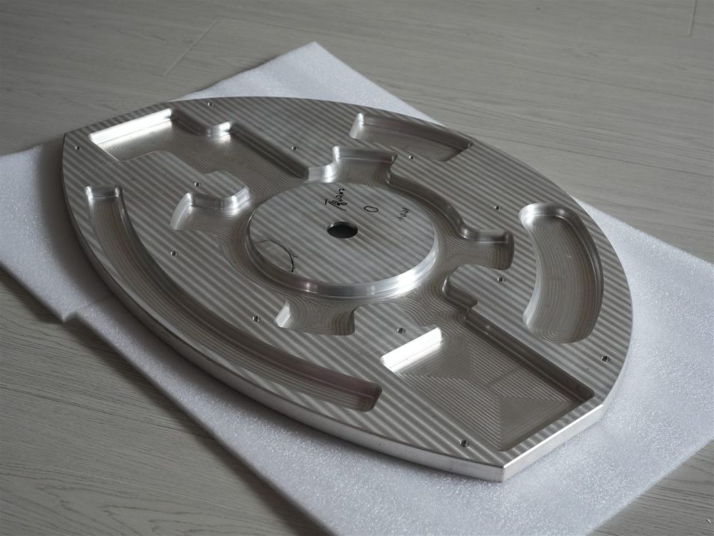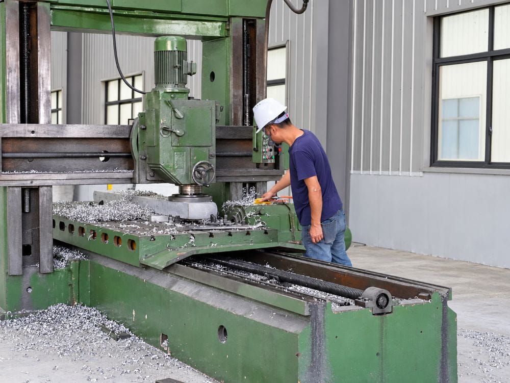
A 3-axis CNC machine moves on the X, Y, and Z axes. It is a practical choice for plates, brackets, pockets, and parts whose features can be reached from one direction at a time. A 5-axis machine adds two rotary movements, so it can reach several faces with fewer re-clampings. That helps on some difficult parts. It does not make five-axis the automatic answer for every precision job.
If you are new to the process, start with our guide to what CNC means in manufacturing. The machine configuration is only one part of a CNC route; stock shape, fixturing, tooling, inspection, and annual volume matter too.
3-axis and 5-axis machine movement
On a three-axis mill, the cutter and table move in straight X, Y, and Z directions. The workpiece is normally held in a vise or fixture. The machine can face the top, mill a profile, drill holes, cut pockets, and machine slots very well. To work on a side or the underside, the operator usually stops the machine and changes how the part is held.
That is not a weakness. Plenty of production parts are best made this way. A flat aluminum enclosure, a mounting bracket, or a plate with a clear hole pattern does not become better simply because it went onto a five-axis machine. A stable three-axis setup is often fast, straightforward to inspect, and easier to quote.
Five-axis equipment has the same three linear movements plus two rotary axes. Depending on the machine, the table may tilt and rotate, the spindle may swivel, or both. The extra motion lets the tool approach angled faces without repeatedly removing the part from the fixture.
There are two common ways shops use this capability. In 3+2 machining, the table is indexed to an angle and locked while the cut is made. In simultaneous five-axis machining, the rotary axes keep moving during the cut. A 3+2 setup is useful for angled holes, compound faces, and multi-sided work. Simultaneous motion is usually reserved for continuously changing surfaces, such as impellers, blisks, and certain aerospace or medical components.
The label on the machine is less important than the work it actually removes. Some parts only need one indexed angle. Others need the tool to keep a controlled angle across a curved surface. Those are very different programming jobs.
3 axis vs 5 axis CNC: the shop-floor comparison
The table below compares the normal working differences. These are process facts, not promises about every machine or supplier.
| Factor | 3-Axis CNC | 5-Axis CNC |
|---|---|---|
| Controlled movement | X, Y, and Z linear axes | X, Y, Z plus two rotary axes |
| Best fit | Flat, prismatic, and moderately complex parts | Multi-face parts, angled features, and complex surfaces |
| Part handling | Often requires turning or re-fixturing for additional faces | Can reach several faces in one clamping when the geometry allows |
| Programming | Usually simpler | More complex; collision checks matter more |
| Machine rate | Usually lower | Usually higher |
| Tool approach | Mostly normal to the setup face | Can use angled approaches and shorter tool reach in many cases |
| Typical parts | Plates, brackets, simple housings, fixtures | Impellers, turbine-style parts, complex housings, aerospace structures |
A drawing can make the answer obvious. A rectangular electronic housing with pockets on top and clearance holes on the sides may be made on a three-axis mill with two or three setups. If the side-hole location is loose and the volume is small, that can be the sensible route.
Now take a small magnesium housing with ports on several nonparallel faces, a sealing surface around a compound angle, and positions that must stay related. Repositioning it three times can create risk and take time. That is the sort of part where five-axis access deserves a serious look.
Accuracy comes from the whole setup
Five-axis machining is often described as “more accurate.” That is too broad. The real benefit is frequently fewer setup changes. Each time a part is removed and clamped again, the shop must locate it from a datum, protect finished surfaces, and confirm that the fixture is holding it without distortion. A second or third setup adds opportunity for small positional differences to build up.
If several critical faces can be completed in one five-axis setup, their relationship may be easier to control. This is useful for angled bores, intersecting sealing faces, or features that must stay located to a common datum. It also helps when a long tool would otherwise be needed to reach around a wall. A shorter, more rigid tool can improve the cut.
But a simple part can be highly accurate on a good three-axis machine. Machine condition, thermal stability, tool wear, workholding, material stress, and the inspection method all affect the final measurement. Putting a square plate with four holes onto a five-axis machine does not automatically improve it.
For a deeper look at those terms, see CNC accuracy vs. precision vs. repeatability. When tolerances are tight, also agree on the inspection method early and compare it against the CNC machining tolerance chart. A tolerance is only useful if it can be measured in a repeatable way.
One detail sometimes gets missed: free-state parts and clamped parts can read differently. Thin plates, long rails, and light magnesium structures may relax after machining. The drawing should make clear whether flatness or position is checked unsupported, on a fixture, or against a functional mating part.
Setups, tool access, and cost
The hourly rate for a five-axis machine is commonly higher than for a three-axis mill. That is real, but it is not the whole cost calculation. A five-axis route can remove two or three fixtures, reduce manual handling, and shorten the total lead time. On another part, its extra programming effort may add cost with no practical return.
Consider a part with a top pocket, two side ports, and an angled hole. A three-axis shop may finish the top in the first fixture, rotate the part for the side ports, then build an angled fixture or use a separate setup for the hole. That route can work well. It just needs time for every clamp, touch-off, and inspection step.
On five-axis equipment, the same part may remain in one fixture while the table positions each face. If those ports and the angled hole relate to the same sealing face, the route can be cleaner. If they do not carry tight relationships, the added capability may not earn its keep.
| Cost driver | What it changes in a 3-axis route | What can change in a 5-axis route |
|---|---|---|
| Number of machined faces | More faces can add setups | Several faces may be reached from one clamping |
| Tool reach | Deep or angled features may need long cutters or special fixtures | Tilting the tool can improve access and reduce overhang |
| Feature relationship | Each re-clamp must be located from a datum | Common features can often be cut from one reference position |
| CAM and prove-out | Usually shorter programming time | More programming, simulation, and collision review |
| Quantity | Simple fixtures are often enough for low quantities | Setup savings can matter more as repeat volume rises |
Material plays into this discussion, especially where chip evacuation or thin walls are involved. Aluminum is forgiving in many layouts. Titanium often benefits from rigid tool engagement and careful heat control. Magnesium alloys machine readily, but the shop still needs suitable chip collection, housekeeping, and fire-safety procedures. The part geometry should be reviewed along with the alloy and starting form.
Parts that belong on five-axis machines
Five-axis is a strong option when the tool cannot reasonably approach the required feature from a vertical direction. Examples include compound-angle holes, undercut-like features that can be reached by tilting the tool, sculpted surfaces, and deep pockets surrounded by tall walls.
Impellers are the familiar example because the blades change angle continuously. Aerospace brackets and structural parts can also justify five-axis machining when they have several lightened pockets and important features on many faces. Complex optical, medical, and automotive components often fall into the same category.
It can be helpful on a complex housing, too. Imagine a housing with connector openings on three sides, an angled cable exit, and a gasket land that must remain related to the mounting face. A five-axis fixture may hold the part once while the tool gets to each area. That does not erase the need for good datums or inspection, but it can avoid a stack of workarounds.
Five-axis is less compelling for a flat plate, a simple mounting bracket, or a one-sided pocketed part. Those parts generally belong on a three-axis machine unless there is a specific access or positional reason to do otherwise. More axes are not a substitute for a simple manufacturing plan.
Choosing a route before the quote
The most useful question is not “Can this be made on a five-axis machine?” Almost any part can be. The better question is whether five-axis access removes a real setup, tolerance, or tool-reach problem.
Before you send the drawing, look at the following points:
- How many faces need machining, and which ones are functional?
- Are there angled holes, compound surfaces, or features behind a wall?
- Do critical features need to stay related after the part is repositioned?
- Would a very long, small cutter be required on a three-axis setup?
- Is the order a prototype, a short production run, or a repeat program?
The answers do not need to be perfect. They give the manufacturing engineer a better starting point. A supplier may still recommend a three-axis route, a 3+2 setup, simultaneous five-axis machining, or a redesign of one difficult feature.
For a quote, provide a STEP or other usable 3D file, a controlled 2D drawing, the material grade, quantity, critical tolerances, finish or coating, inspection requirements, and required delivery date. If a feature has a functional reason, such as a sealing face or bearing location, say so. That information is often more valuable than a note demanding five-axis machining.
Common questions
What is the main difference between 3-axis and 5-axis CNC?
Three-axis machines cut with X, Y, and Z linear motion. Five-axis machines add two rotary movements, allowing the cutter to reach more angles and faces without as many re-clampings.
Is 5-axis CNC more accurate than 3-axis CNC?
It can improve the relationship between several features when it removes setup changes. Final accuracy still depends on the machine, workholding, tool, material, temperature, and inspection plan.
Is 5-axis machining more expensive?
The machine and programming rate are usually higher. A five-axis route can still be the lower total-cost choice when it removes fixtures, handling, long-tool problems, or multiple setups.
Can a 3-axis machine make complex parts?
Yes. Many complex-looking parts are made with several three-axis setups. The limitation appears when access, setup count, or feature relationships make that route inefficient or risky.
What is 3+2-axis machining?
The machine uses two rotary axes to place the part at an angle, then locks them while cutting with the three linear axes. It is common for angled features and multi-face work.
When is five-axis unnecessary?
It is usually unnecessary for parts with one main setup face, ordinary holes and pockets, or features that can be reached with simple re-fixturing without compromising important dimensions.
Can magnesium be machined on a five-axis CNC machine?
Yes. The same access and setup logic applies. The shop should also confirm alloy, chip-management practice, coolant approach where applicable, and its magnesium safety procedures before production.