AZ80A magnesium forging is a practical option for lightweight parts that need more strength than a general-purpose wrought magnesium grade can provide. It is commonly considered for structural brackets, hubs, housings, arms, and similar components where a forged grain flow and low mass both matter. The part still has to be designed for forging. A sharp inside corner, a sudden wall change, or a critical face with no machining allowance can turn a promising material choice into a difficult die and finishing job.
AZ80A sits in the higher-strength end of the familiar magnesium-aluminum-zinc wrought alloys. It is not a replacement for every casting or machined billet. Forging is worth considering when the annual volume, loading, geometry, and required part integrity justify the tooling and development work.
What AZ80A brings to a forged part
AZ80A is a magnesium alloy with aluminum, zinc, and manganese. Its aluminum level is higher than AZ61A, and it responds well to artificial aging after fabrication. That combination is why AZ80A is often used for stronger forged magnesium components rather than for parts that need extensive room-temperature forming after delivery.
The material starts as controlled billet or forging stock. A supplier’s billet quality matters because grain structure affects how the metal fills the die and how repeatable the finished part will be. That is a billet-supply statement, not a finished-part guarantee, but it shows why the material source belongs in the early conversation.
In a forged part, the useful properties come from more than alloy chemistry. Billet preparation, preheat, die temperature, deformation amount, cooling, aging, and later machining all leave a mark. A compact axle bracket can behave very differently from a wide frame member even when both parts are marked AZ80A-T5.
This is why a forged part should not be specified with a single tensile number copied from a website. The buyer needs the alloy, product form, condition, governing specification, and acceptance requirements. The forger needs the drawing, section map, machining allowance, and realistic annual volume.
Die shape, section changes, and the first forging trial
Magnesium has a narrower practical forming window than steel or aluminum in many forging jobs. The details belong with the forger’s qualified process, but the drawing can either make that work easier or create a problem before the billet is heated.
Start by looking at section transitions. A heavy boss beside a thin web does not fill and cool like a uniform section. The die designer may need a preform, controlled flow path, flash land, or a sequence of operations to move material where it belongs. A component that looks simple in CAD can need more than one hit if the grain flow or cross-section changes are demanding.
Inside corners matter. A very small radius raises local strain and can drive up die loads. It also gives the finishing cutter less room later. When a generous radius will not affect function or assembly, it usually makes life easier for both the die shop and the machine shop.
Parting-line position needs the same attention. The line should sit where flash can be removed without damaging a critical sealing or locating surface. If a part must be machined after forging, the drawing should show where the forger can leave stock. Calling out a finished surface right up to a raw-forged edge may look efficient on paper, but it can leave no room to correct die variation or remove the forge skin.
The first trial is where assumptions become visible. A sound review checks fill, flash, surface condition, grain direction where relevant, and whether the forging still has enough material on the machining faces. For a demanding part, it is normal to make a development forging before the final die route is released. That work is cheaper than discovering an unfillable rib or a drifting bore after production tooling is complete.
T5 is usually part of the AZ80A forging route
AZ80A is commonly supplied in the T5 condition for high-strength forged work. In broad terms, T5 means the forging is cooled from an elevated fabrication temperature and then artificially aged. This is different from a T6 route, which includes solution heat treatment and quenching before aging.
The distinction matters because a second high-temperature cycle can affect structure and dimensional control. A study of AZ80A model forgings found that its T5 condition retained higher mechanical properties than its T6 condition under several of the tested forging and heat-treatment routes. In its 400°C model-forging condition, the T5 specimens reached 366 MPa ultimate tensile strength and 293 MPa yield strength, while the T6 specimens reached 333 MPa and 241 MPa. Those are research results for a specific process, not a guaranteed property range for every forging. The published study is still useful because it shows why the temper needs to be matched to the actual route.
On a real order, the material certificate and the applicable specification control. ASTM B91-17 lists minimum tensile requirements for AZ80A-T5 forgings of 290 MPa ultimate tensile strength, 193 MPa yield strength, and 2% elongation. A supplier may quote higher typical values for a qualified product, but the drawing should not quietly substitute a typical value for the required acceptance level.
| AZ80A-T5 forging data point | Ultimate tensile strength | 0.2% yield strength | Elongation | How to use it |
|---|---|---|---|---|
| ASTM B91-17 minimum for AZ80A-T5 forgings | 290 MPa | 193 MPa | 2% | Purchase-order baseline when that standard applies |
| Published AZ80A-T5 forged-alloy reference | 345 MPa | 250 MPa | 11% | Typical reference; verify product form and test direction |
| Model forging study: 400°C forging, T5 | 366 MPa | 293 MPa | 11% | Research result for that exact chemistry and process |
The gap between those rows is normal. They describe different sources, sample conditions, and purposes. The ASTM line sets a minimum for a named specification. The other numbers help engineers understand what has been achieved in controlled material and process conditions. They are not interchangeable.
If the application has fatigue loading, elevated temperature, pressure retention, or a certification requirement, add that to the RFQ. A general room-temperature tensile certificate may not answer the question that actually controls the part.
For a deeper explanation of the temper choice, read AZ80A-T5 vs AZ80A-T6. It covers the extra T6 thermal cycle and the possible effect on final machining allowance.
Leave the right stock for machining
Many AZ80A forgings are not finished at the die. They may need bores, mounting holes, threads, bearing seats, flat pads, sealing faces, or cosmetic milling. That work needs to be planned while the forging is still being designed.
Machining allowance should appear where it earns its keep. A bore that controls a bearing fit needs enough material for a stable final cut. A wide mounting face may need a clean machining pad after aging. A surface that will receive coating may need a different approach from a raw-forged exterior that is acceptable as it comes from the die.
Do not spread extra stock everywhere just to be safe. Oversized machining allowance increases billet use, forging load, tool time, and chip volume. It can also distort a light part if most of the material is removed from one side. The better approach is to leave stock on the faces that carry a real tolerance or finish requirement and avoid needless cleanup cuts elsewhere.
Workholding is part of the same discussion. A large magnesium forging may look stiff until one side is pocketed. If the part must remain flat after unclamping, the shop may rough it, let it relax, and then finish the important faces. A fixture that supports a broad floor and locates from stable datums can matter more than a faster cutter.
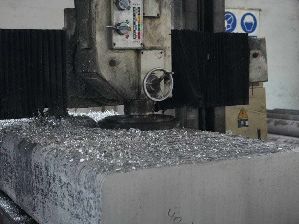
AZ80A itself machines readily, but magnesium chips need appropriate handling. The machine shop should already have documented controls for combustible metal chips, collection, cleanup, cutting fluid, and fire protection. The buyer does not need to prescribe the shop’s equipment. Asking whether the supplier has a documented magnesium-machining process is a reasonable qualification step. Our AZ80A CNC machining guide covers the tooling and chip-control side in more detail.
Coating and corrosion protection belong in the same quote
Forging does not remove magnesium’s need for corrosion planning. A raw AZ80A surface can be suitable in a controlled dry environment, but many finished parts need conversion coating, anodizing, paint, sealed coating systems, or another approved finish. The right answer depends on service environment, mating materials, fasteners, drainage, abrasion, and the customer’s specification.
The issue often shows up at the assembly rather than in the forging cell. A magnesium part next to a dissimilar metal fastener in a wet joint can create a corrosion problem even when the forged part and its machining dimensions were perfect. If there are stainless fasteners, aluminum brackets, copper contacts, or bonded inserts, list them. The coating supplier needs that context.
Specify which faces must remain bare for electrical contact, bonding, bearing fits, or sealing. If a machined surface is coated after final sizing, the coating thickness may affect the fit. If it is masked, the mask line may need a permissible location. These are small notes that keep the forging, machining, and finishing suppliers working from the same picture.
What to send with an AZ80A forging inquiry
The RFQ does not need to tell the forger how to run the press. It needs to state what the finished part must do.
- 2D drawing and 3D model, including the material standard and AZ80A condition
- Finished-part mass, annual quantity, and expected program length
- Critical load areas, grain-flow concerns, pressure-tightness needs, and inspection requirements
- Raw-forged versus machined surfaces, machining allowance, datums, and surface-finish callouts
- Required heat treatment, material certificate, coating, corrosion environment, and mating materials
Add images of the assembly if the geometry is unusual. A supplier can read a drawing, but a view of the part’s load path or its installed position often makes a difficult section transition easier to discuss.
AZ80A magnesium forging makes the most sense when the finished part benefits from a strong, lightweight wrought route and the design has room for a proper die, heat treatment, and final machining sequence. Before choosing a forging route, compare it with the needed product form and component function. The AZ80A magnesium alloy page is a starting point for material options, and the AZ80A vs AZ61A guide helps when the alloy grade itself is still open.