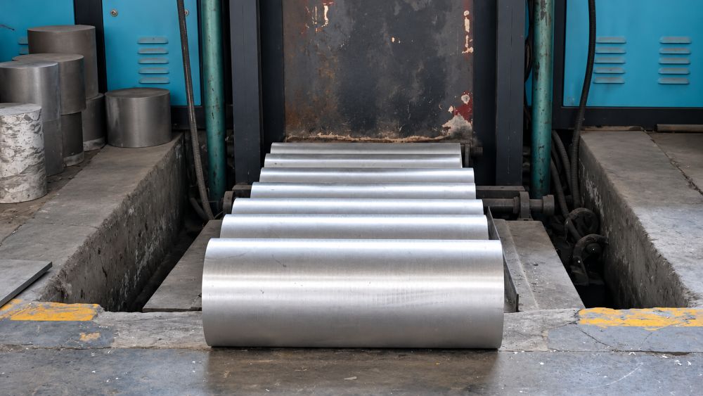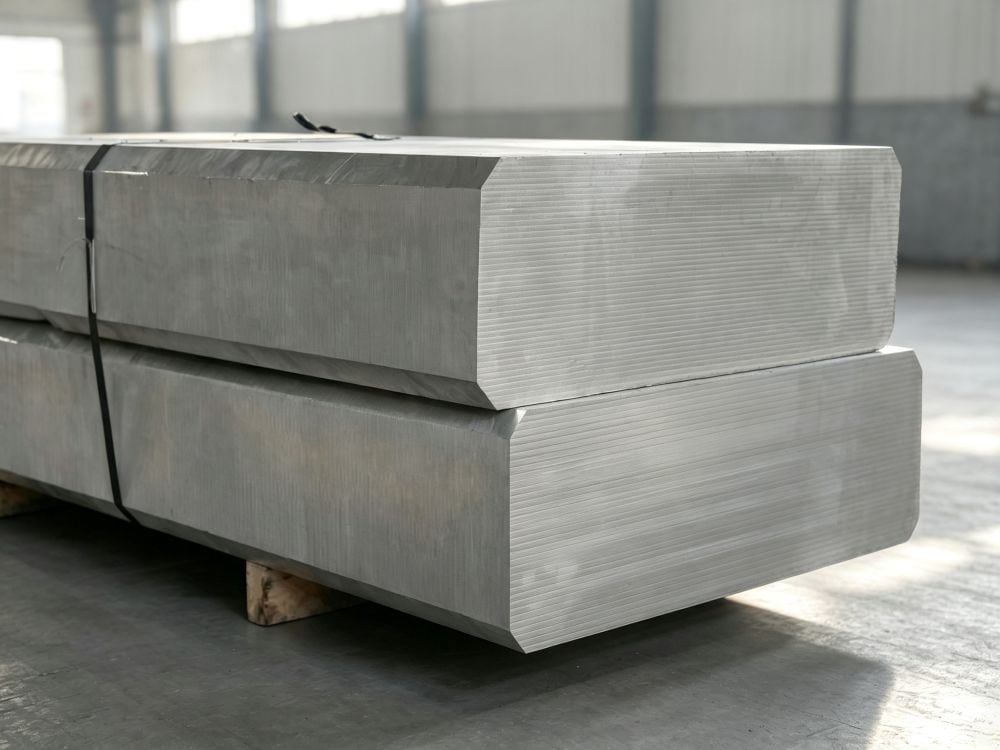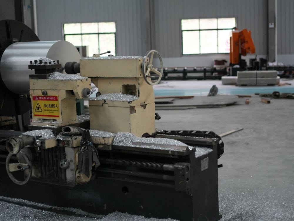
CNC machining AZ80A magnesium is usually straightforward from a cutting-force standpoint. The material cuts freely, and sharp carbide tooling can remove stock quickly. The harder part is running the job in a way that keeps the part stable, produces manageable chips, and follows a real combustible-metal safety plan. For AZ80A extrusions, bar, or forgings, the first setup should be based on the supplied temper, wall thickness, machining allowance, and the shop’s approved chip-handling process—not a speed copied from an unrelated magnesium job.
Workholding thin AZ80A parts
AZ80A is a wrought magnesium alloy, most often seen in extrusions, bar, and forgings rather than as a die-cast material. It is commonly chosen when the part needs more strength than a general-purpose wrought magnesium grade can provide. It may arrive in a strengthened condition, such as T5, or in another condition called out by the order.
That condition matters before the first chip is made. A heavy forged blank and a thin extruded rail can both carry an AZ80A callout, yet they do not behave the same way in a vise. The forging may be rigid enough for a large face mill. The rail may spring once a deep pocket opens up one side.
The usual early mistake is treating magnesium like a very soft block of aluminum and rushing into a high-speed program. Cutting force is low, but a light wall can still chatter or rub. Rubbing makes heat, makes fine swarf, and leaves the operator with a finish problem that did not exist in the CAD model.
Workholding deserves a short review before programming. Locate on surfaces that will remain stable after roughing. Use enough support under a broad floor. If a feature must stay flat after unclamping, say so on the drawing and leave enough material for a finish pass after the main stress-relieving cuts. A part that measures flat while bolted down tells only half the story.
The same thought applies to long extrusions. If the profile will be cut into short parts, drill a pattern of holes, and receive a large pocket, the starting straightness may not be the final straightness. It is better to discuss that before the material is ordered than to debate a free-state flatness result after machining.
Carbide tooling and chip evacuation
Sharp, free-cutting tools are the starting point. Magnesium does not reward a dull edge, a packed flute, or a tool that sits and rubs at the end of a pass. Carbide is widely used for production work; PCD can be appropriate for repeat jobs where the tool economics make sense. The practical detail is not the label on the tool box. It is whether the edge is sharp, the flute space clears chips, and the setup stays rigid.
For pocketing and profiling, a short solid-carbide end mill with ample chip space is usually easier to control than a long-reach cutter. Start with the shortest tool that reaches the feature. If the model forces a 6×D or 8×D tool just to reach one internal corner, that is a design conversation, not a reason to force the program harder.
AZ80A does not need a delicate, rubbing finish pass by default. On a supported part, a positive feed and a clean cut often give the better result. On a thin wall, back the cut down until the wall is no longer singing against the tool. The shop may give up some material-removal rate to keep the part cool, steady, and on size. That is a normal trade on a lightweight structural component.
Drilled holes need the same common sense. A deep hole in a magnesium part is not the place to ignore chip evacuation. The drill geometry, peck strategy, hole depth, coolant or air system approved by the shop, and the way chips exit the cavity all matter. Blind holes and intersecting passages should be shown clearly in the model. They can become chip traps if the machining sequence is left vague.
For threads, identify the thread standard, class, usable depth, and whether the thread carries a fastener directly or receives an insert. Thread engagement in magnesium is a design issue as much as a tapping issue. A supplier needs to know whether a stripped thread is merely an assembly nuisance or a safety-critical failure mode.
AZ80A milling speeds and feeds
Magnesium supports high cutting speeds, but spindle speed by itself is not a machining plan. Tool diameter, flute count, radial engagement, depth of cut, overhang, part stiffness, and the machine’s enclosure all change the safe and useful result.
The table below is a real example from OSG’s solid-carbide AE-TL-N cutting-condition brochure. OSG lists AZ80A within the magnesium-alloy material group. These entries are for a 6 mm, 3×D tool with the stated operation and water-soluble coolant; they are not a general recipe for every AZ80A part or every coolant system. The table is useful because it shows why a slot, a side cut, and a plunge should not all be programmed as the same event.
| OSG AE-TL-N 6 mm solid-carbide reference | Cutting speed | Spindle speed | Table feed | Published setup note |
|---|---|---|---|---|
| Slot milling, 3×D flute length | 240 m/min | 12,800 rpm | 1,520 mm/min | 1×D axial depth |
| Side milling, 3×D flute length | 240 m/min | 12,800 rpm | 1,900 mm/min | 1.5×D axial depth; 0.2×D radial width |
| Plunging, 3×D flute length | 70 m/min | 3,680 rpm | 400 mm/min | 1×D axial depth |
OSG notes that its figures assume a rigid machine and holder and should be adjusted for larger cuts, lower rigidity, longer overhang, or high-precision work. That is exactly how they should be used. A shop running a rigid, enclosed production cell may land on a different stable window than a shop cutting a long, thin AZ80A profile in a fixture with limited support. See the OSG cutting-condition brochure for the original tool-specific data.
Luxfer MEL’s machining guidance makes the same broader point: magnesium’s low cutting force can allow high rates, while part stability, chip extraction, tool limits, and clamping usually set the real boundary. Its guide lists general turning and boring ranges of 200–1,800 m/min and face-milling speeds up to 3,000 m/min for magnesium, with clear warnings that drilling, reaming, and tapping are different operations. Those are broad process ranges, not AZ80A acceptance values. Use the current toolmaker recommendation and prove the setup on the actual material form. Luxfer’s guide is useful background for that review.
The first approved part should answer a few ordinary questions: Is the finish consistent at the end of the tool life window? Does the part move after unclamping? Are chips leaving the pocket? Can the measurement be repeated using the datums on the drawing? If any answer is no, changing the programmed feed is only one possible fix. The fixture or toolpath may be the actual problem.
Magnesium chip handling and fire safety
This is the part no responsible shop treats as an afterthought. Fine magnesium dust, chips, and shavings are combustible. OSHA identifies metal dusts, including magnesium, as a combustible-dust concern, and its technical manual points to NFPA 484 for processing and finishing operations that generate combustible metal powder or dust. OSHA’s combustible-dust guidance covers the scope at a facility level.
For the machining cell, that means the chip-management method, collection equipment, cleanup routine, approved cutting fluid, fire-protection equipment, training, and emergency response need to be set by the facility’s documented magnesium program. This is not a place to improvise with whatever coolant, vacuum, or extinguisher happens to be nearby. OSHA notes that fires involving combustible-metal powders, flakes, or shavings such as magnesium require Class D extinguishers. Its extinguisher guidance is a useful basic reference; the shop’s site-specific emergency plan controls the actual response.
The machining choices connect directly to that plan. Keep cutters sharp. Avoid dwelling or rubbing. Do not create piles of fine swarf by running an unsuitable finish strategy. Clear chips in the approved way, keep the machine and surrounding area clean, and do not mix AZ80A chips into a general scrap stream without the recycler’s and facility’s stated procedure.
The buyer does not need to dictate safety equipment to the machine shop. The buyer should ask one direct question: “Do you have a documented process for machining and collecting magnesium chips?” A qualified supplier should be comfortable answering it before they quote the job.
Drawing details for machined AZ80A parts
The print should give the shop the details that change the setup. A material callout without form or temper is incomplete. A flatness note without saying whether the part is checked free-state or supported can send inspection in the wrong direction. Deep pockets, blind holes, and intersecting passages deserve a clear view in the model because they affect both programming and chip removal.
- Give the AZ80A standard, supplied form, temper, and certificate requirement.
- Mark the few surfaces that truly control the assembly: pads, threads, bearing seats, and post-coating features.
- Show the pockets and holes that may hold chips, then identify the corrosion system and mating fastener materials.
- Add expected quantity and any required first-article, CMM, or traceability record.
That is usually enough for the supplier to decide whether extruded stock, bar, a forging, or a near-net blank makes sense. It also explains why two quotes for the same model can come back with different fixture and inspection allowances.
AZ80A is not difficult to machine because it is magnesium. It becomes difficult when a lightweight part asks for tight geometry after most of its supporting material has been removed. A sound drawing, a sharp cutter, stable workholding, and a shop that already has its magnesium safety process in place go a long way.
If the production route is still open, review the AZ80A magnesium alloy options alongside the planned magnesium CNC machining work.