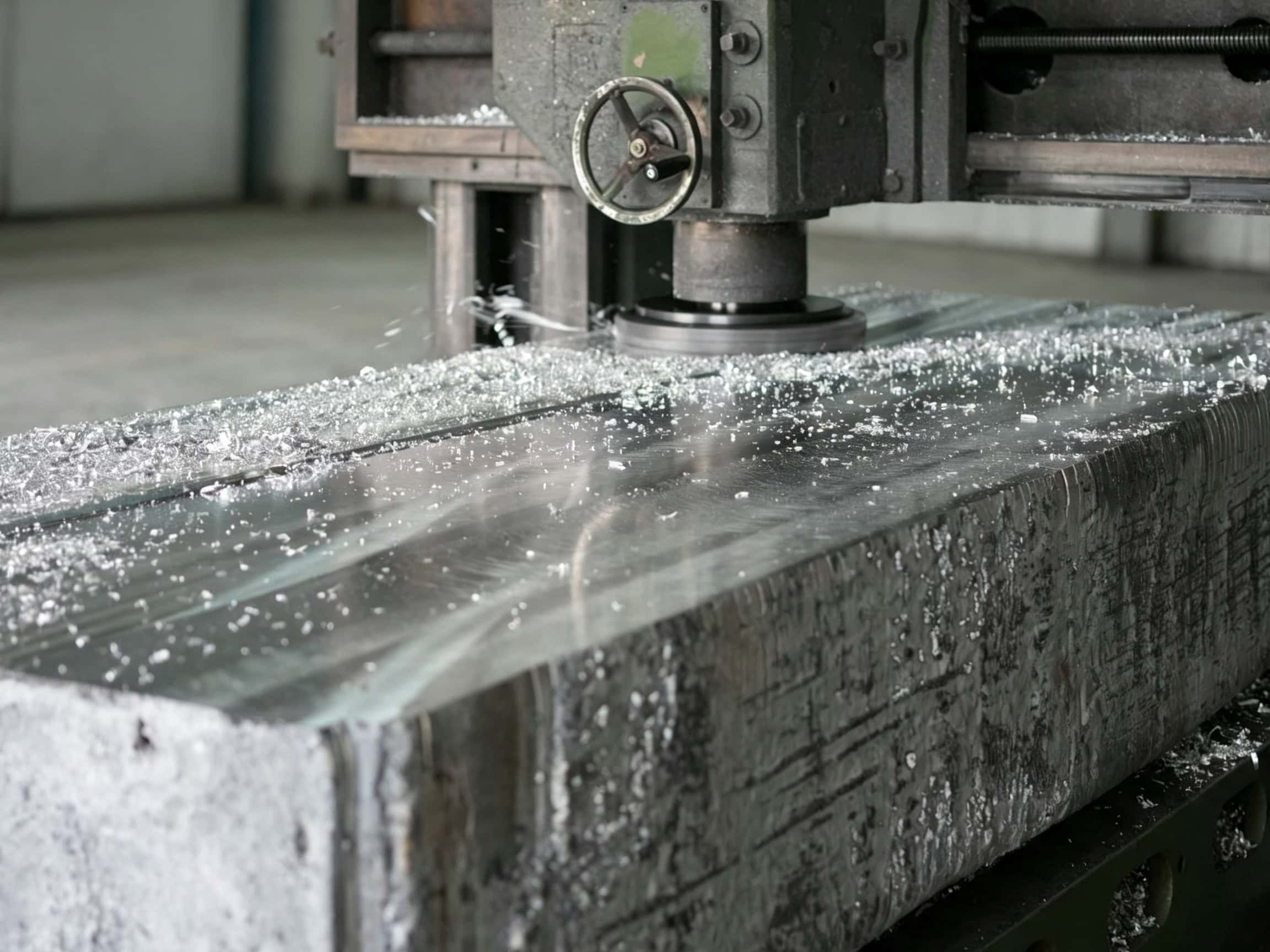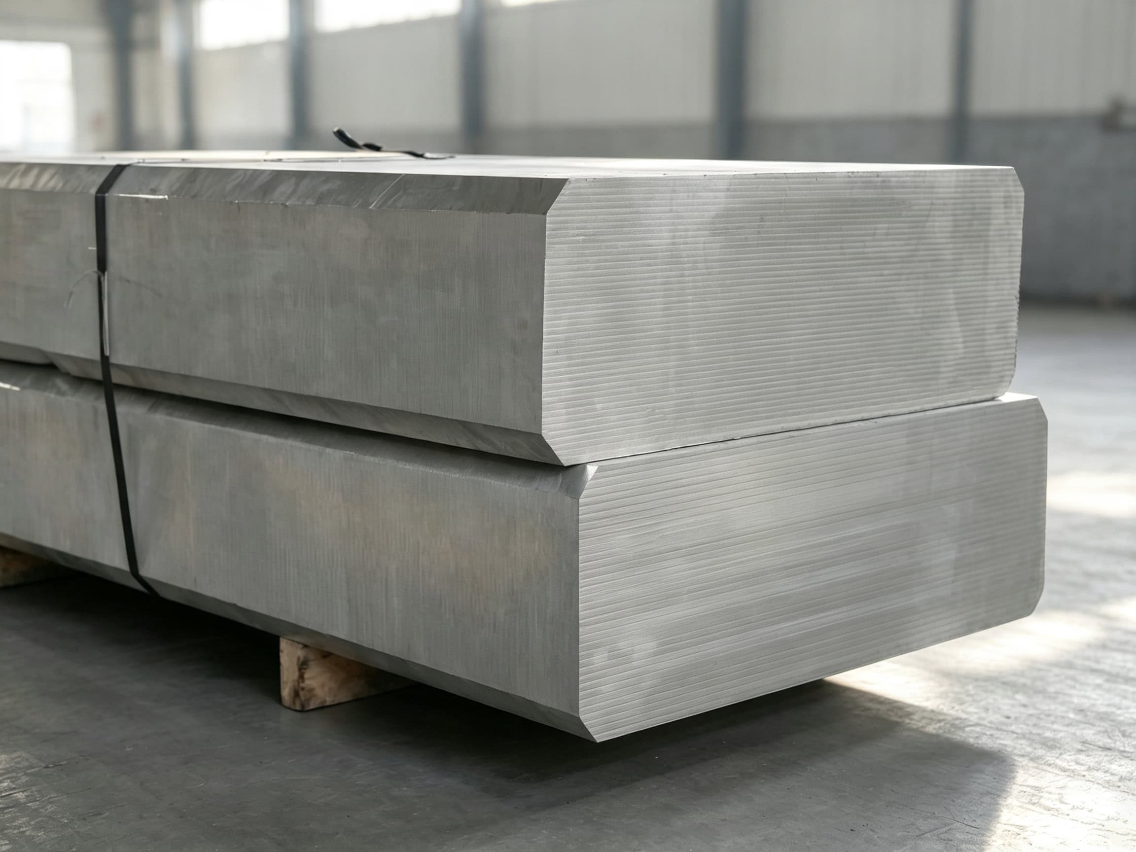

CNC machining magnesium alloys (such as AZ31B, ZK60, AZ80A, and WE43) provides unmatched manufacturing advantages for lightweight structural components in aerospace, automotive racing, robotic arm linkages, and 3C electronics. With extremely low cutting resistance (only 1/6th of steel and 1/2 of aluminum) and high thermal conductivity, magnesium allows for ultra-fast material removal rates (MRR), prolonged cutter lifespan, and sub-micron surface finishes (Ra < 0.4 μm).
However, successful precision machining and global procurement require strict protocols regarding tool geometry, speeds and feeds parameters, chip fire safety management, and subsequent corrosion-resistant surface engineering, particularly Micro-Arc Oxidation (MAO/PEO) and anodizing. This technical engineering guide details the machining protocols and surface treatment standards implemented at Miji Magnesium‘s precision manufacturing facility.
1. Recommended Speeds, Feeds & Tool Geometry for Magnesium CNC Milling
Because magnesium generates very low cutting forces, high spindle speeds and heavy feed rates are highly recommended. Heavy feeds ensure that chips are thick and carry away friction heat, preventing local temperature buildup near the ignition threshold (450°C).
| CNC Machining Operation | Tool Material | Cutting Speed Vc (m/min) | Feed Rate fz (mm/tooth) | Axial Depth of Cut ap (mm) |
|---|---|---|---|---|
| Rough Face Milling | Uncoated Solid Carbide | 600 – 1200 m/min | 0.15 – 0.35 mm/z | 2.0 – 6.0 mm |
| Finish Face Milling | PCD (Polycrystalline Diamond) | 800 – 1800 m/min | 0.05 – 0.15 mm/z | 0.2 – 0.8 mm (Ra < 0.4 μm) |
| Side / Shoulder Milling | Carbide End Mill (2-Flute) | 400 – 900 m/min | 0.08 – 0.20 mm/z | Up to 1.5× Diameter |
| High-Speed Turning | Carbide / PCD Insert | 300 – 800 m/min | 0.10 – 0.30 mm/rev | 0.5 – 4.0 mm |
| Deep Hole Drilling | Carbide Twist Drill (118°-135°) | 100 – 250 m/min | 0.08 – 0.25 mm/rev | Peck cycle with active air blast |
Optimal Tool Geometry Guidelines:
- Rake Angle (γ): Keep large positive rake angles (15° to 25°) to produce smooth shearing with minimal tool friction.
- Relief Angle (α): Generous clearance angles (10° to 15°) prevent the tool flank from rubbing against the spring-back elastic recovery of magnesium workpieces.
- Helix Angle & Flutes: Use 2-flute or 3-flute end mills with polished flutes (helix angle 30° to 45°) to provide maximum chip evacuation space. Never use 4+ flute cutters designed for steel, which trap fine magnesium dust.
2. Magnesium Chip Fire Prevention & Workshop Safety Protocols
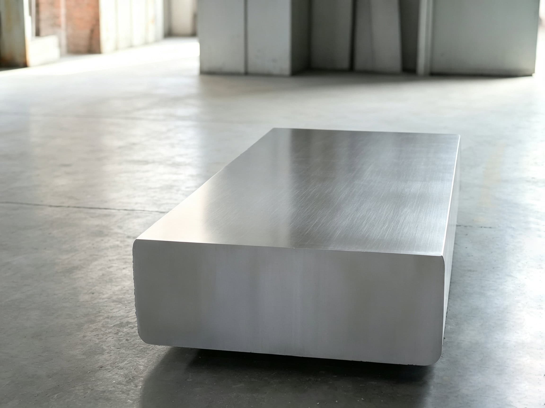
While solid magnesium blocks and heavy tooling plates are virtually non-combustible at room temperature, fine magnesium swarf, thin shavings, and airborne dust can ignite if exposed to friction sparks or high localized cutting temperatures. Miji Magnesium strictly enforces ISO 45001 safety measures:
- Coolant Selection (CRITICAL): NEVER USE WATER-BASED COOLANTS OR EMULSIONS. Magnesium reacts with water at elevated temperatures to release flammable hydrogen gas (Mg + 2H2O → Mg(OH)2 + H2 ↑). Machining should be performed with dry cold air blast or high-flashpoint mineral-oil-based cutting fluids (Flashpoint > 160°C).
- Keep Cutters Razor Sharp: Dull tools cause rubbing rather than cutting, rapidly spiking friction heat. Replace inserts promptly upon tool wear detection.
- Continuous Chip Evacuation: Do not allow magnesium chips to accumulate in machine tool enclosures. Vacuum chips continuously with explosion-proof wet collectors or air extractors.
- Class D Fire Extinguishers: Standard water, foam, or CO2 extinguishers must never be used on burning magnesium. Keep certified Class D dry powder (sodium chloride / copper flux based) or dry flux sand adjacent to every CNC machining center.
3. Corrosion Resistance & Surface Finishing: MAO, Anodizing & Chemical Passivation
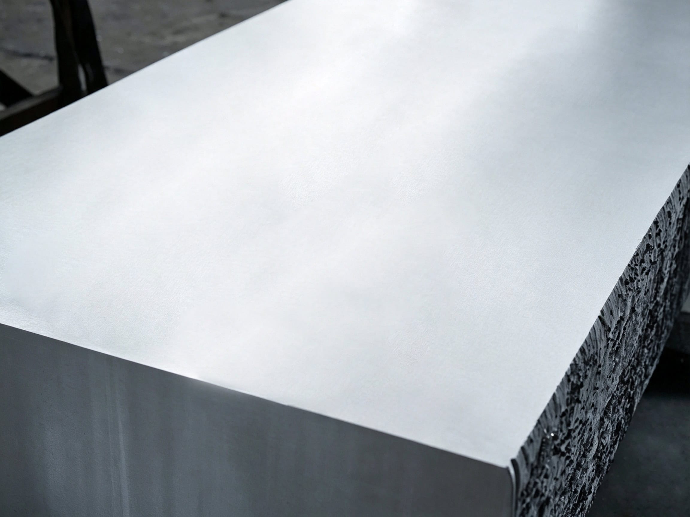
Due to magnesium’s standard electrode potential (-2.37 V), bare magnesium alloys require protective surface engineering for harsh automotive chassis, marine, and outdoor environments. We offer four industry-certified surface finishing solutions:
| Surface Finishing Process | Layer Thickness | Microhardness (HV) | Neutral Salt Spray (NSS) Rating | Primary Engineering Benefits |
|---|---|---|---|---|
| Micro-Arc Oxidation (MAO / PEO) | 10 – 35 μm | 800 – 1200 HV | 500 – 1000 Hours (No Pit) | Dense ceramic MgAl2O4 phase; extreme wear resistance & dielectric insulation. |
| Hard Anodizing (Type III) | 15 – 25 μm | 400 – 600 HV | 240 – 480 Hours | Uniform oxide barrier, excellent adhesion primer for topcoat paint. |
| Electroless Nickel Plating (ENP) | 12 – 30 μm | 500 – 900 HV | 168 – 360 Hours | Full metallic sheen, high electrical conductivity & EMI shielding attenuation. |
| Chromate-Free Chemical Passivation | 1 – 3 μm | Substrate level | 48 – 96 Hours (In-transit) | RoHS/REACH compliant eco-friendly pre-treatment for powder coating. |
4. Dimensional Inspection, CMM Verification & Tight Tolerances
Because magnesium exhibits a higher coefficient of thermal expansion (26 × 10^-6 / K) than steel (12 × 10^-6 / K), precision machining is conducted inside climate-controlled temperature workshops (20°C ± 1°C). Every finished 5-axis CNC structural component is inspected on Zeiss 3D Coordinate Measuring Machines (CMM) and optical profilometers:
- Linear & Bore Tolerances: Achievable down to ±0.005 mm (±0.0002″) on multi-axis machining centers.
- True Position & Concentricity: Maintained within 0.010 mm across complex geometric hole arrays.
- Full FAI Documentation: First Article Inspection reports, material batch traceability (OES spectrometer certificates), and 100% CMM dimensional data sheets supplied with every delivery.
5. Turnkey Magnesium CNC Machining: Rapid DFM & 24h Quoting
From initial alloy billet selection (AZ31B, ZK60, AZ80A, WE43) through 5-axis CNC machining, deep drilling, tapping, and certified MAO ceramic coating, Miji Magnesium provides end-to-end precision manufacturing solutions under strict NDA protection.
Accelerate your engineering development today: Send your 3D CAD models (STEP, STP, IGES, DXF) to our engineering team at sales@mijimg.com. We deliver comprehensive DFM feedback, toolpath feasibility reviews, and formal production quotations within 24 hours.