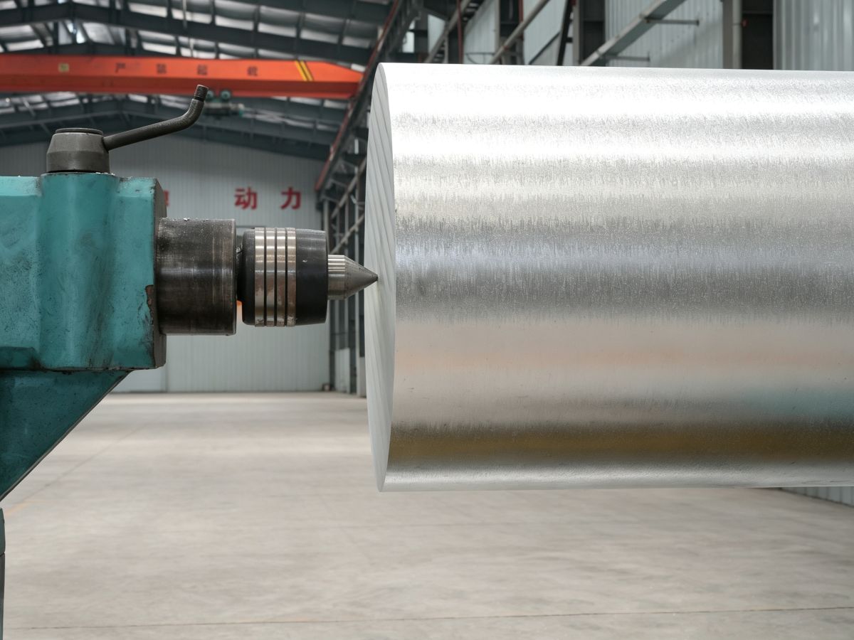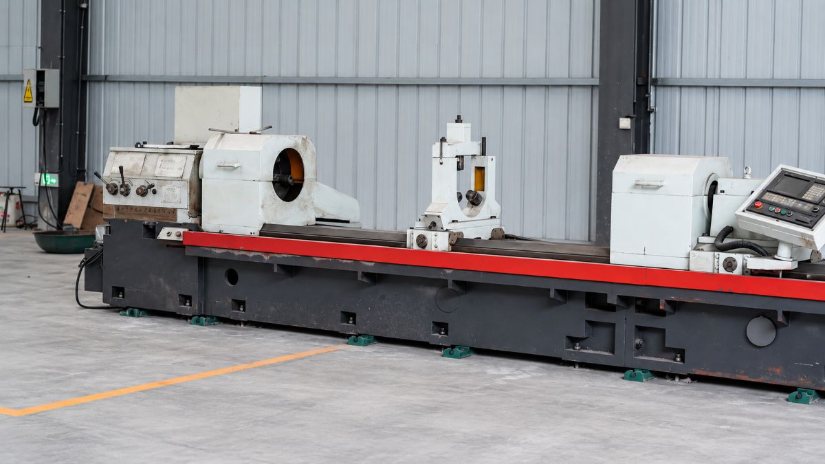
AZ61A magnesium extrusion is a good fit when you need a long, light structural section with more strength than a typical AZ31B extrusion. It is commonly considered for solid profiles, tubes, rails, bars, brackets, and parts cut from extruded stock. The decision still comes down to the section shape, loading direction, wall layout, post-extrusion work, and corrosion environment. Start with the profile and the real load path. The alloy grade follows from there.
AZ61A as an extrusion alloy
AZ61A is a wrought magnesium-aluminum-zinc alloy. It is normally discussed for extruded bars, rod, solid shapes, tube, hollow sections, and forgings. A long part with the same cross-section from one end to the other is where extrusion earns its keep. Think rails, rectangular profiles, channels, round tube, structural frames, and near-net blanks for machining.
It is often chosen when AZ31B is not quite strong enough in the required product form. The difference comes mainly from aluminum content. AZ61A carries roughly 6% aluminum, compared with roughly 3% in AZ31B. That raises strength, but it also means the material is less forgiving when a design depends on aggressive cold forming after extrusion.
The useful feature of an extrusion is the section itself. A well-placed rib, a closed box, or a pair of flanges can do more for stiffness than adding material to a flat wall. This is worth settling early. A profile that looks easy in CAD can turn into a difficult die if it has deep narrow pockets, unsupported lips, abrupt wall changes, or several cavities that do not flow at the same rate.
For standard material information and available supply forms, see AZ61A magnesium alloy. For a broader process overview, see magnesium extrusion.
Solid AZ61A profiles are usually the simpler place to start. Flat bars, rounds, channels, angles, and open shapes do not require an internal mandrel. Hollow profiles and tubes can save substantial weight, but the die design is more involved and dimensional control deserves a direct discussion with the extrusion supplier.
Do not describe a hollow section only as “tube” if its inside shape matters. Put the internal geometry, minimum wall, critical outside faces, straightness requirement, twist limit, and any zones that will be machined on the drawing. Those details affect the die and the straightening plan.
Section design, walls, and direction
Most extrusion problems show up first at an uneven section. A heavy flange joined to a thin web does not cool, straighten, or respond to machining the same way as a balanced profile. Large differences in wall thickness can also make the metal flow unevenly through the die.
Try to keep wall changes gradual. Use generous internal radii where the function allows it. A sharp re-entrant corner is not free in extrusion, and it may become the point where later machining or coating exposes a problem. If a sharp corner is truly functional, it is often better to leave material there and machine the feature afterward.
There is no honest one-number answer for minimum wall thickness. It depends on the profile size, alloy condition, die layout, press capability, length, flatness requirement, and whether the profile will be straightened or machined. A thin open fin and a thin wall in a small closed tube are not the same manufacturing problem. Send the cross-section before locking a wall callout.
Extrusion direction matters to the finished part. Wrought magnesium develops directionality during processing, and tensile data are commonly reported along the extrusion direction. If a bracket is loaded across the profile rather than along it, say so. If a tube will be flattened, bent, or drilled across a thin wall, show that operation in the drawing package. It changes the discussion from “Can you extrude this?” to “Will this section work after the next operation?”
For a profile that will be cut into short parts, specify whether the extrusion end condition is relevant. Saw-cut blanks, long bars, and finished CNC parts have different inspection points. A requirement for a pristine cut face or a tightly controlled finished length may belong in the secondary-operation route, not in the raw extrusion tolerance.
AZ61A-F composition and published data
The chemical limits below are from ASTM B107/B107M for AZ61A wrought extrusion material. The alloy is magnesium balance with aluminum, zinc, and manganese as the main specified additions.
| Element | ASTM B107/B107M AZ61A requirement, wt.% |
|---|---|
| Aluminum | 5.8–7.2 |
| Zinc | 0.40–1.50 |
| Manganese | 0.15–0.50 |
| Iron | 0.005 max |
| Copper | 0.05 max |
| Nickel | 0.005 max |
| Silicon | 0.10 max |
| Magnesium | Balance |
F means as fabricated. It is a condition designation, not a promise that every profile, size, test direction, or mill route will return the same mechanical result. Request the applicable standard and a current material certificate with the order.
Published AZ61A-F values vary by product form and section size. One published data set for extruded AZ61A lists 310 MPa tensile strength, 230 MPa 0.2% yield strength, and 16% elongation. ASTM B107 lists lower minimum values—255 MPa tensile and 145 MPa yield—for solid extrusions in its 6.3–60 mm size range. Both numbers can be useful, but they answer different questions.
The first set is a published property reference for an extruded product. The second is a purchase-specification floor for a defined product category. If a rail is being sized for load, use the required project basis and the mill certificate. A catalog value should not quietly become the design allowables for a finished profile.
Density is commonly listed at about 1.80 g/cm³ for AZ61A. That low density is why an extruded section can be attractive in a frame, support, instrument component, or transport assembly. It does not remove the need to check stiffness. Magnesium’s elastic modulus is much lower than steel’s, so a light profile often needs a section shape that makes good use of depth and closed geometry.
Cutting, straightening, machining, and joining
Extrusions do not always leave the press in their final shape. Long sections can need straightening before they are cut. A profile with an unbalanced cross-section may carry residual stress, and a later milling pass can reveal movement that was not obvious on the long length.
This is common with broad, thin sections. The profile may sit flat while supported, then change slightly after a pocket is milled or after the last clamp is released. If free-state flatness is important, put that on the drawing. Do not assume that a measurement taken while the part is fixtured answers the same question.
AZ61A machines well, but magnesium machining requires a planned setup. Keep cutters sharp, avoid rubbing, and make sure chips are cleared rather than packed into a pocket. Chip collection, housekeeping, compatible coolant or dry-machining practice, and fire control are part of the job. They should be agreed with the machine shop before production, especially where deep pockets or high-volume chip generation are involved.
Use the extrusion as close to net section as practical. It can reduce machining time and material waste. At the same time, leave enough stock where a functional face needs to be trued. It is a poor trade to buy a complicated thin-wall profile and then remove most of it on a mill because the locating surfaces were never defined.
AZ61A is generally weldable by gas and arc processes. That does not mean a weld detail can be added at the end of the project without consequences. A weld changes the local heat history, may require stress relief depending on the specification and service, and can make corrosion protection more difficult. Show the joint type, expected load, access side, filler or process if it is prescribed, and coating sequence. In a corrosion-sensitive assembly, isolating magnesium from dissimilar metals and controlling moisture paths are usually just as important as the weld itself.
Coating and die cost
Bare magnesium should not be treated as a finish for a wet, salty, or galvanically active service environment. The coating system needs to match the exposure. Conversion coatings, anodic processes, paint systems, and other specified treatments are selected by the part’s use, required appearance, contact surfaces, and the materials fastened to it.
If an AZ61A profile will touch aluminum, steel, stainless steel, or copper-containing hardware, flag it in the design review. Water trapped at a joint can create a more serious problem than the broad exposed face of the profile. Use isolation, sealing, compatible fasteners, and a coating sequence that fits the assembly.
Tooling cost depends mainly on profile complexity, size, tolerance, and whether the section is solid or hollow. A simple open section may justify extrusion at moderate volume. A complex multi-void hollow profile needs a stronger volume case because the die work and development effort rise. Ask for a die-feasibility review before you freeze the drawing; it is less expensive than changing a released section after a first trial.
AZ31B is often the more practical starting point when the work begins with sheet or needs meaningful forming. Our earlier AZ31B vs AZ61A magnesium comparison covers that choice in more detail. AZ61A is more often considered when the part is fundamentally an extrusion or forging and needs a higher strength level.
For an initial extrusion review, a dimensioned section, length, alloy condition, expected quantity, and any straightness, machining, or coating constraints are usually enough to expose the first die and process questions.
Data note: Composition limits are from ASTM B107/B107M. Published mechanical values are reference values for stated product forms and conditions; use the applicable specification and mill certificate for procurement and design release.